New Leffakone Infrared Receiver
Käännös: [ Google ]
Kategoriat: [ Askartelu/Arduino | TV/Leffakone ]
Several months ago, the leffakone infrared receiver started to misbehave. There were a lot of errors in syslog about spikes in the signal, and the problem seemed to come from the serial port on the motherboard rather than from the homebrew IR receiver, connected to the serial port, that I had built in 2002 or 2003 and that I had been using with lirc ever since. One of the symptoms was that unloading the lirc-serial kernel module caused the computer to freeze, while testing the receiver with an oscilloscope seemed to show that it was working correctly. For many months, I was too lazy to do something about it, as using a keyboard with a long enough cord was enough to control leffakone. During the last autumn vacation, I tried to test the receiver with the serial port on minikone, but the latter seems to deliver only 1.2V signals, when the receiver expects at least 7V to power its onboard voltage regulator. So that was not very conclusive.
At the same time, I had the idea of building a CO2
monitor
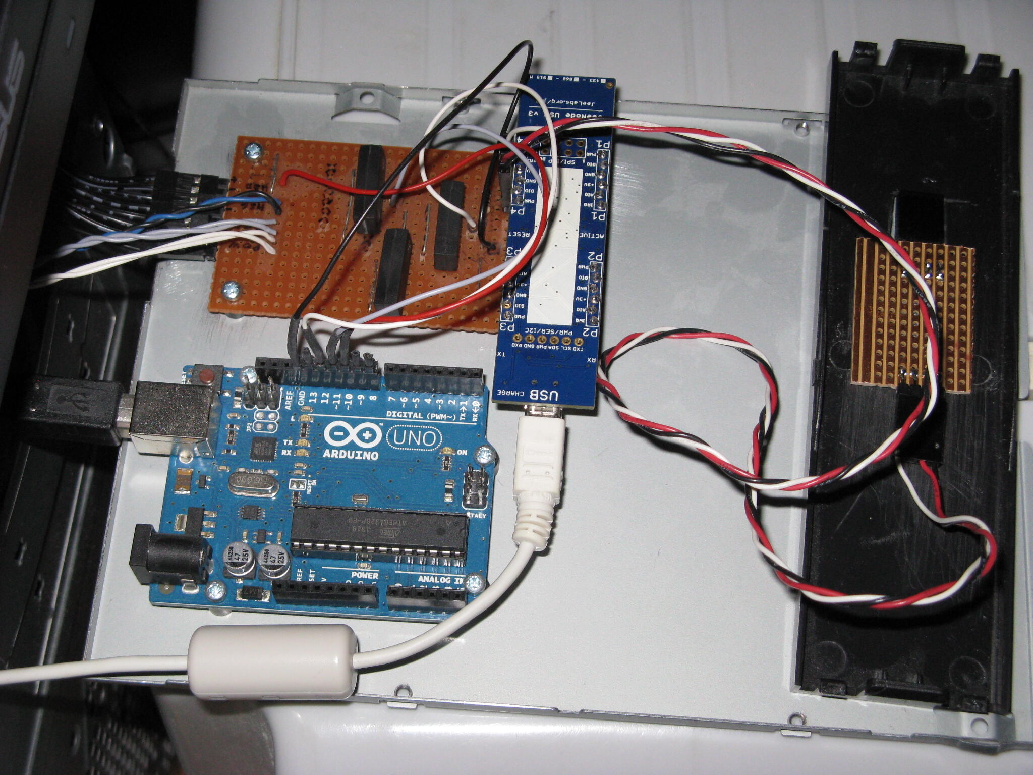
using a Jeenode I had lying around, and somehow I wondered if the IR receiver
module would not just fit into one of the Jeenode's ports. Guess what? It
fits perfectly, allowing to use the IRQ pin as the input, which is exactly
what the Arduino-IRremote
library suggests to use. Writing the software
was a bit of a headache, because the library assumes that the compiler would
run with the -flto option (and the compilation ends with an error if it is
not set), but my custom Makefile somehow fails to compile the code correctly
if I enable that option. Thankfully, you can get around the problem with
#define SUPPRESS_ERROR_MESSAGE_FOR_BEGIN. After that, the program is quite
straightforward: configure it for the RC5 protocol (as this is what my remote
control produces), read a code and write it to the serial port if it matches
the RC5 address. I also added a new feature: if the code is the power on
button, it would set a pin to HIGH for a short while, allowing to switch the
computer on. I used the Jeenode USB
as it has an on-board USB-to-serial adatpter, which makes it perfect to
connect to a modern computer. I had one reed relay left from the
timer
and despite being rated for a 5V control voltage, it works with the Jeenode's
3.3V signal. The Jeenode is connected to the computer with a USB cable where I
have replaced the USB Type A connector with a Molex connector so that I can
use one of USB headers on the motherboard. Crimping the very small contacts
was difficult as I don't have a crimping tool, but the connections seem to be
working despite having done quite a poor job of it.
Yesterday, I installed the extra reed relay and the Jeenode onto the PCB that holds the relays of the timer, and now it's inside leffakone and working well. And since I forgot to take a picture, there is no image of what it looks like. In addition, I'm quite happy I have been able to do this project by using only bits and pieces I already had (the Jeenode, the headers, the reed relay, the IR receiver module, the USB cable, the Molex contacts and housing).
[ Postattu 14. marraskuuta 2021 klo 11.56 | ei kommenttia | kestävä linkki ]
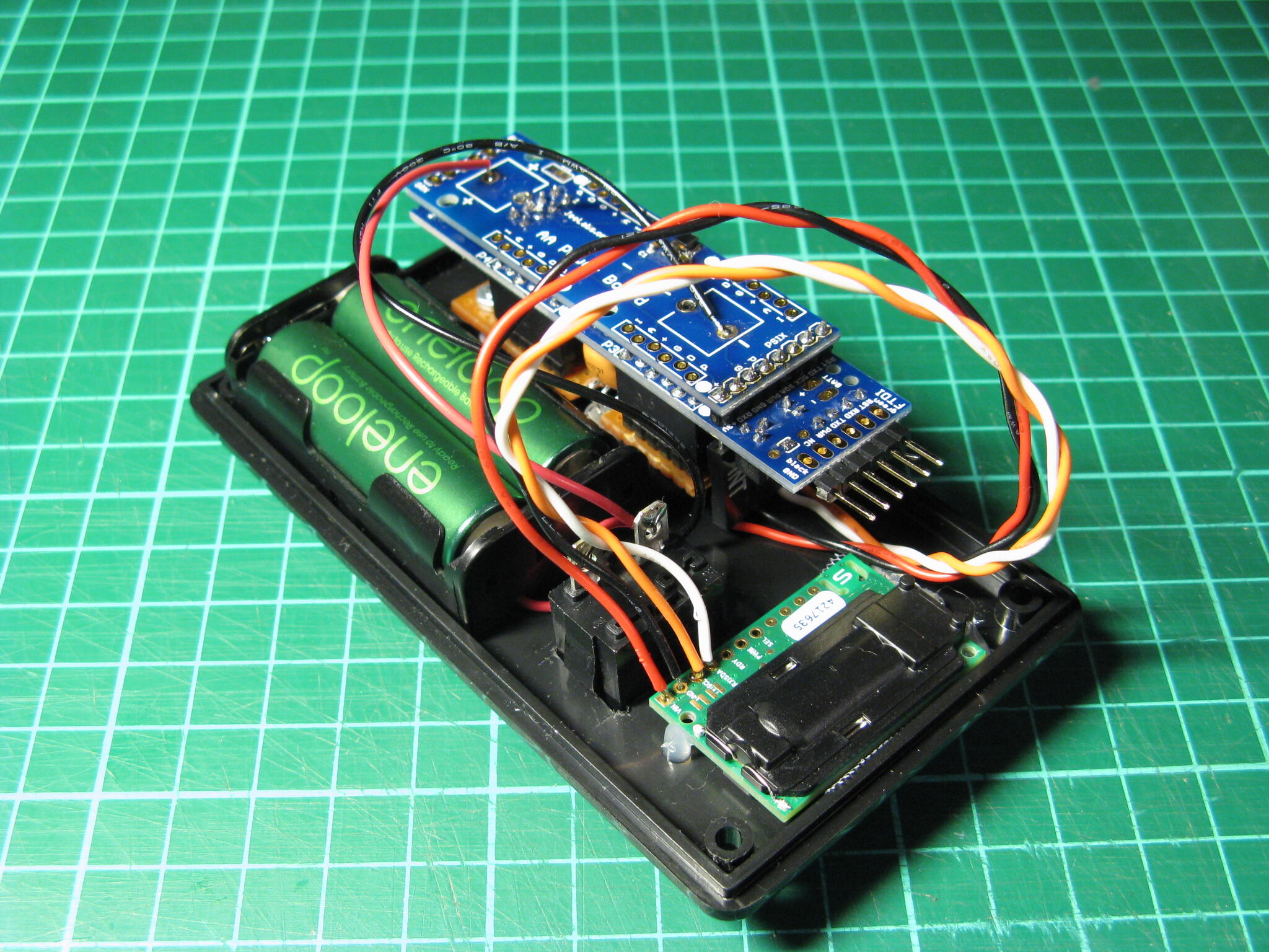
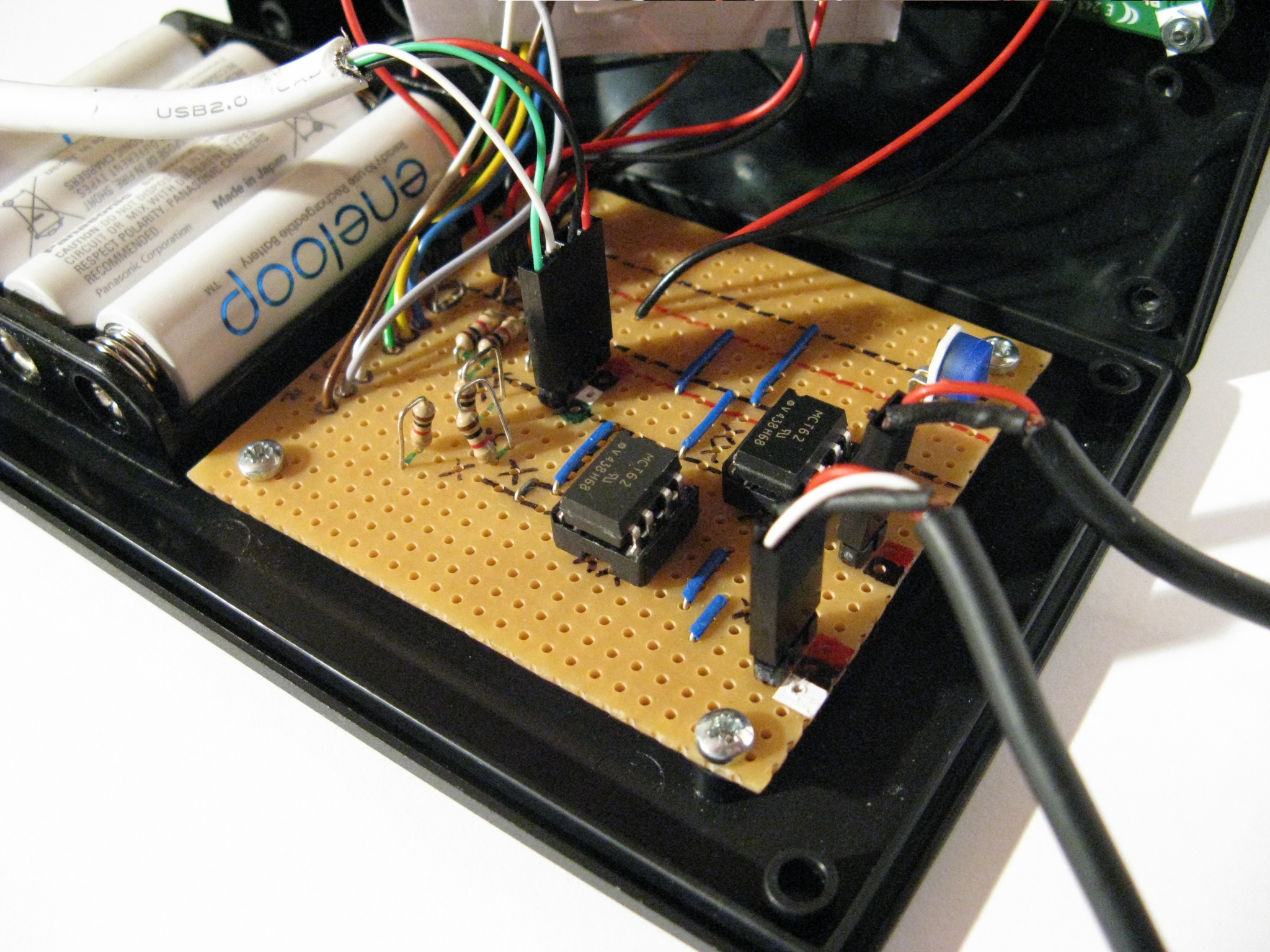
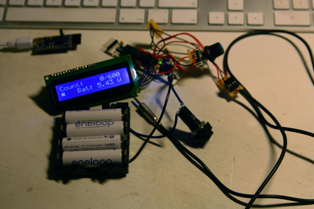


It actually ran about 33 hours on one pair of Eneloop batteries. That's much more than my first estimate of 25 hours.