Car Heater Controller
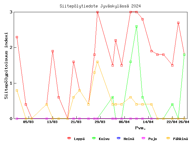
Käännös: [ Google ]
Kategoriat: [ Askartelu/Arduino ]
Finnish winters are cold, and petrol engines don't like starting when it's very cold. That's why cars are often equipped with an electric heater that preheat's the cooling liquid for some time before starting the engine. The duration of this pre-heating depends on the temperature (in French). Moreover, since I don't leave home every morning at the same time, I don't want to start heating the car at the same time every day, even if the outside temperature doesn't change much from day to day. Hence this project of a remote-controlled switch for the car heater.
The system is composed of two Arduino-compatible parts: one master, connected to the home computer (always on), and one slave, in the garage. The master is a JeeLink and the slave is based on a JeeNode. Master and slave communicate with each other with a radio (868 MHz, a free Low-power_communication_device band in Europe).
The master
Not much to say about the master, the hardware is a standard JeeLink, which for the purpose of this project is really only a radio transceiver on a Serial-over-USB interface.
The slave
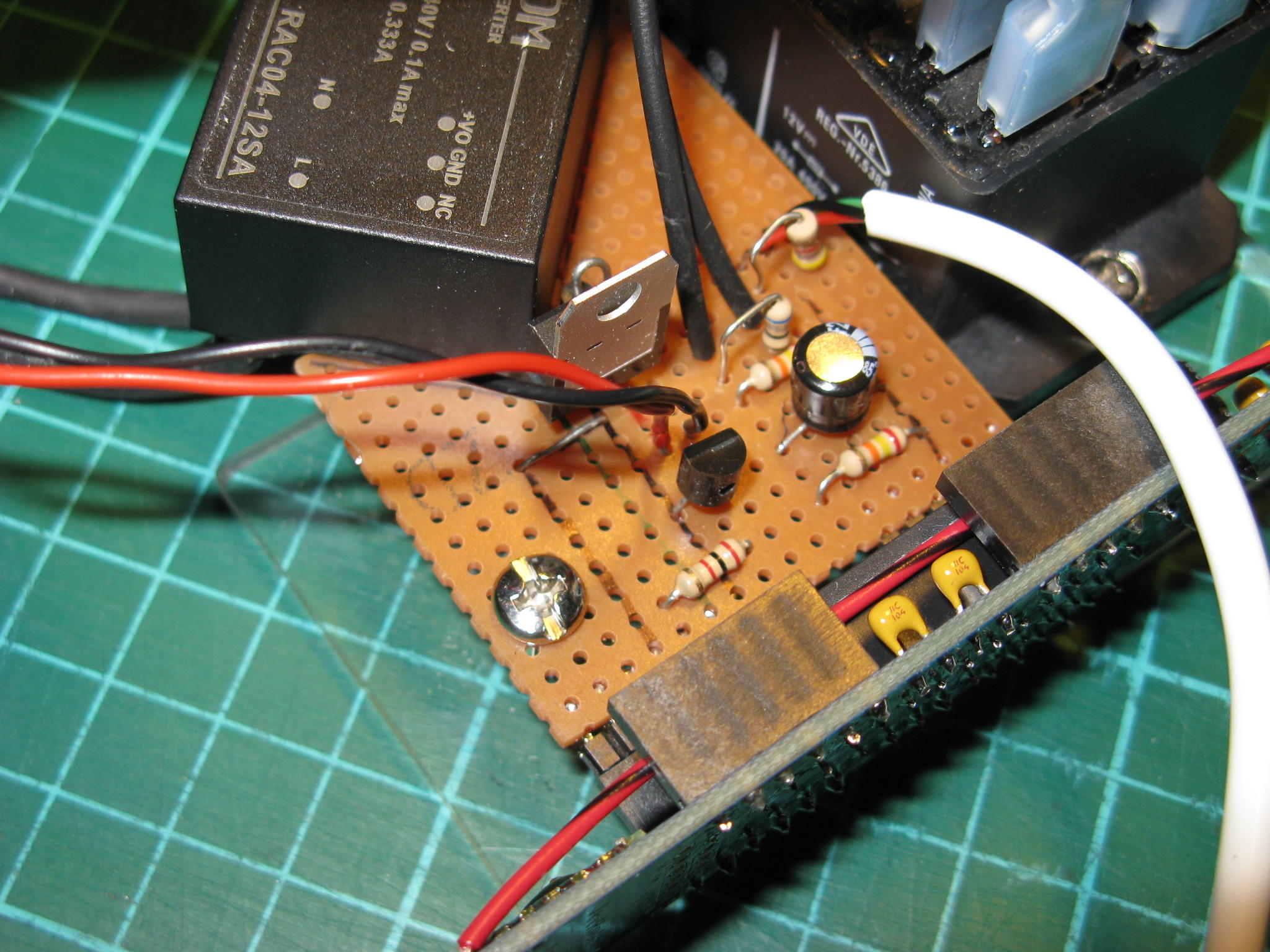
The electronic is very simple, and only a few components are needed. I paid special attention to selecting components that are specified to work from -40 °C (although I have no idea how well the device works at that temperature).
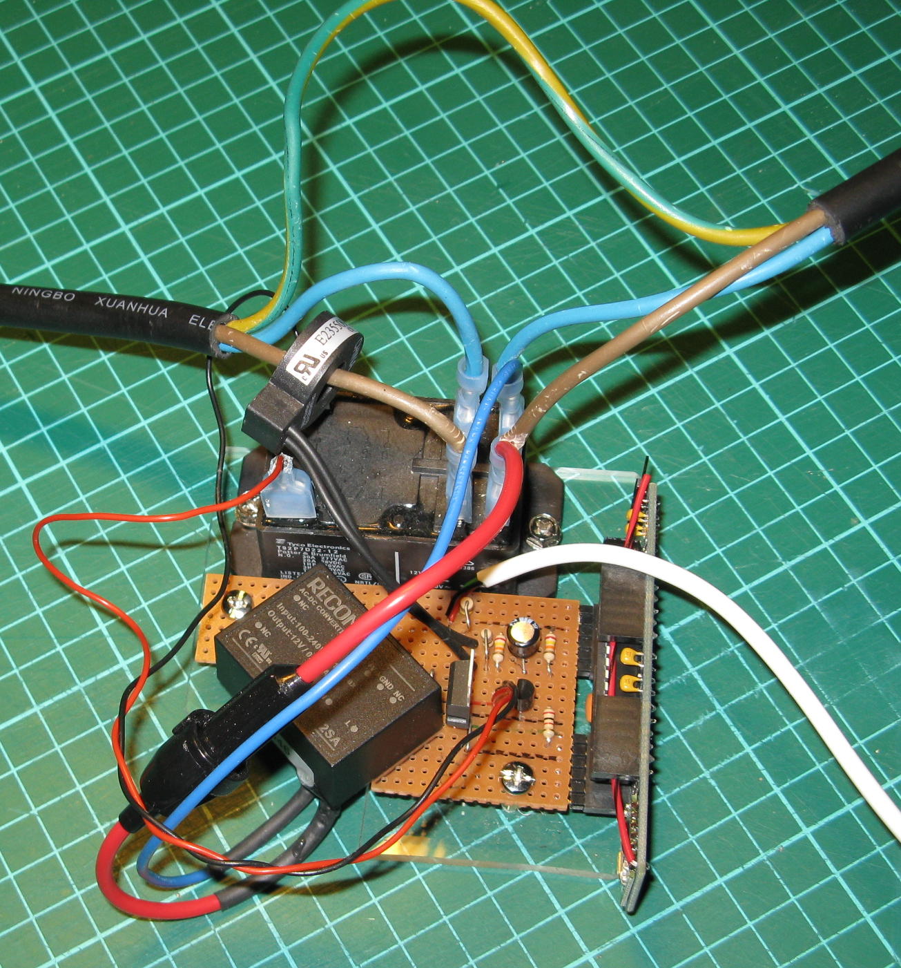
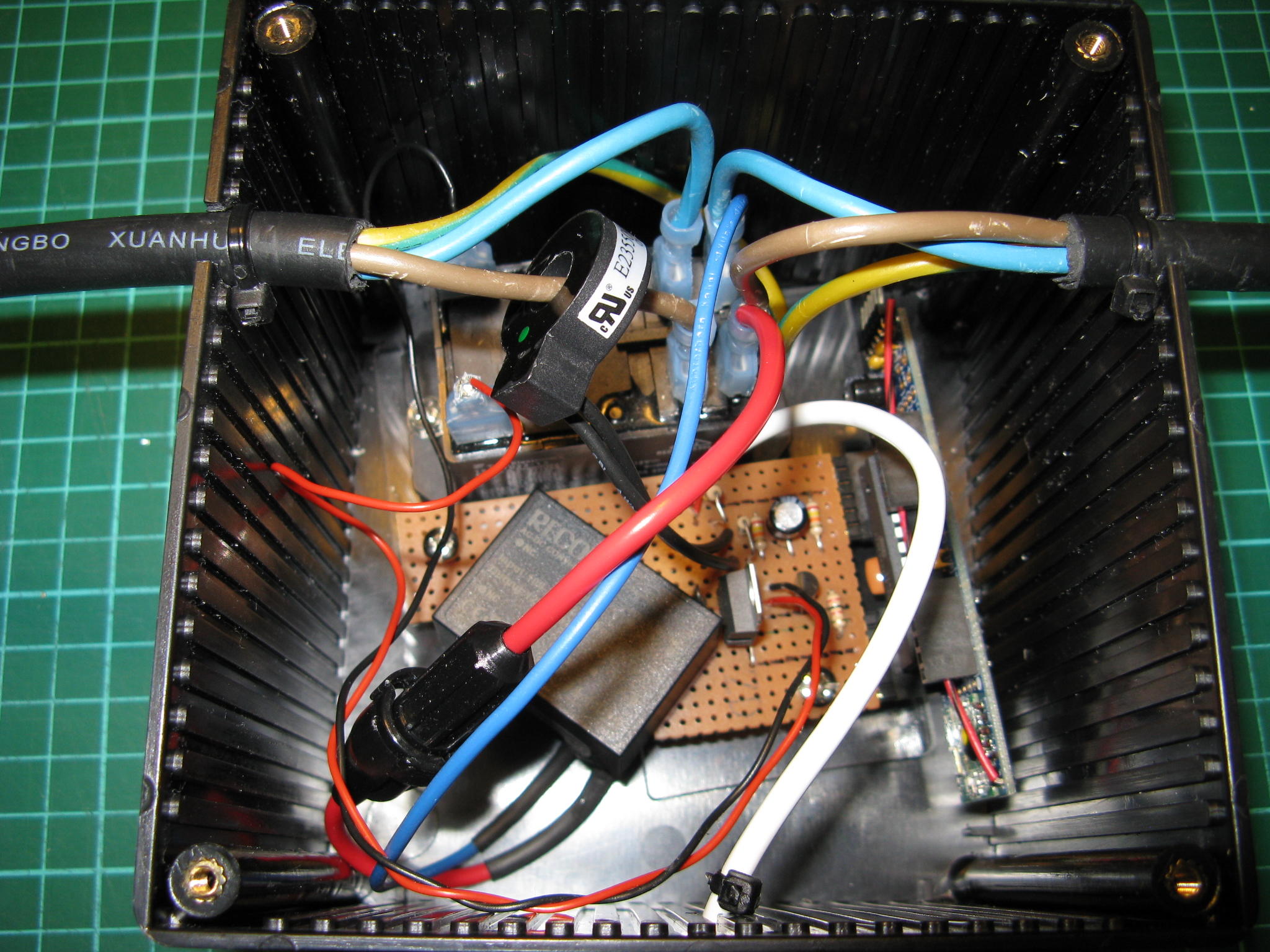
The slave is organised around a JeeNode (vertical, in the right-hand corner of the picture), and has the following three features.
It controls a relay (the black box above the orange PCB on the picture), which can be open or closed.
It measures the outside temperature with a DS18S20 sensor.
It measures the current flowing out of the relay using a current transformer (the black ring aroung the brown wire on the left side of the picture).
Moreover, it has a power supply (the black box on the lower left corner of the picture).
You can also notice that the mains cable (a 5 m, outdoors prolongation cord) has an earth wire that has not been severed. The live (brown) and neutral (blue) wires have been cut and connected to the relay. Power for the power supply is taken from the plug-side of the cable, before the relay (so it's always connected to the mains).
Power supply
The power comes from a compact switching power supply that converts 230 V AC into 12 V DC (maximum output power: 4 W). In case the power supply fails, the 1 A fuse (in the holder on the big red wire on the lower-left corner of the picture) should blow before the whole thing catches on fire. Also, although the power supply is designed to be placed on a PCB, I decided not to have any 230 VAC on the PCB, so I soldered the wires straight to its input pins, and isolated them with heat-shrink tube and added epoxy for strenght (the pins are not so strong, I don't want to break them once they are connected to the thick and not-so-flexible wires).
The relay requires 12 V, hence the output value for the power supply. The JeeNode requires a 3.3 V supply, and the onboard voltage regulator could take the 12 V, but would ouput only a low current (less than 100 mA). By adding a 5 V regulator (7805) to supply the JeeNode, the latter can get more current from its on-board regulator.
Relay
The relay (specified to switch up to 400 VAC and 30 A) requires 160 mA to be activated. It is therefore controlled via a BC337 transistor, which is strong enough to withstand the current. The base of the transistor is connected to one digital pin of the JeeNode via a 2 kΩ resistor, which allows to open or close the relay by applying a High or Low signal to that pin.
Temperature sensor
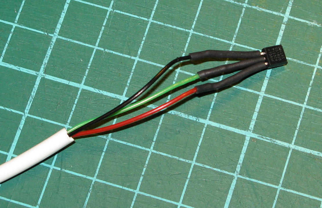
The DS18S20 transmits the temperture information digitally over a 1-Wire bus, and therefore requires really nothing more than a 4.7 kΩ pull-up resistor. It works quite happily with 3.3 V at the end of a 15 m cable (an old phone extension cord). Note that since I have three wires in the cable, I didn't even try to power the sensor with parasitic power (anyway, I read somewhere that it doesn't work well at 3.3 V). The Arduino OneWire library does all the work for you, all you need is to connect the data pin of the sensor to one digital input of the JeeNode.
Current sensor
Finally, the current transformer is placed around the live wire coming out of the relay. The design is based on a page at OpenEnergyMonitor that does not appear to exist anymore, but this one should give a good start.
Basically, the current transformer produces a current (not a voltage) that is proportional (depending on the number of turns, my transformer has 1012 turns) to the current flowing through the mains wire that goes through the transformer. A burden resistor (68 Ω in my case) across the two wires produces an AC voltage that is proportional to this current and varies between -1.65 and +1.65 V (corresponding to mains current between -23 and +23 A peak-to-peak). Then one wire of the transformer is connected to a voltage divider made of two 20 kΩ resistors (with a filtering 47 μF capacitor) and the other wire goes to one of the analog inputs of the JeeNode. This way, the analog input sees a voltage that varies between 0 and 3.3 V, which is within the tolerance of the device.
After that, the software samples the analog value 3000 times, applies a high-pass filter to remove the DC offset, and simple math computes the RMS current. After a bit of calibration (using a 60 W lamp, and 500 W halogen lamp, a 1400 W flat iron and a 2300 W electric kettle, and comparing my measurments against those of a wattmeter), I noticed that the reported current is quite accurate (to about 0.01 A, which is more than enough for my purposes).
Box
The PCB and the relay a screwed on a piece of plexiglas, and the whole device is placed in a project box to protect it from dust. Zip ties around the cables near the holes prevent the cables from being accidentally pulled out of the box.
Schematics
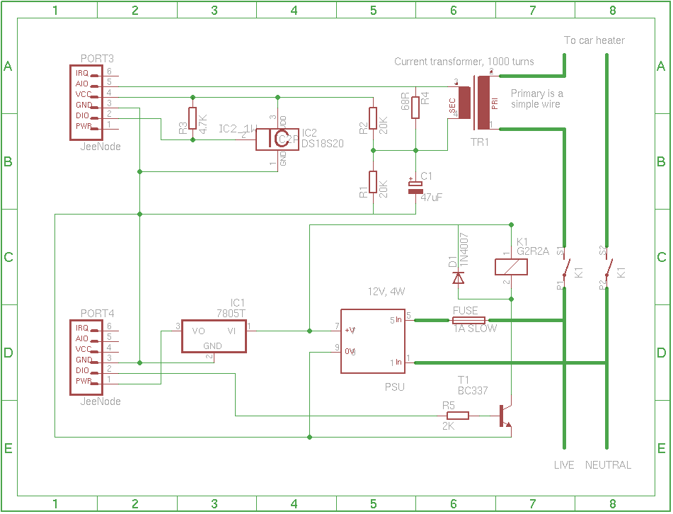
The schematics are available as a PNG picture, and in Eagle format. Note that since I used strip board to assemble the circuit, I haven't paid attention to choosing the right component packages, nor the right type of component. The Eagle schematics is therefore provided for information purposes only, generating a board from it is not going to produce correct results.
The Software
It's all available there. You can obtain it with git using the commandgit clone http://weber.fi.eu.org/software/arduino/heater_controller/.git/
[ Postattu 22. maaliskuuta 2012 klo 23.23 | 1 kommentti | kestävä linkki ]