Current Monitor
Traduction: [ Google | Babelfish ]
Catégories : [ Bricolage ]

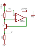
This schematics of a current monitor can be found in many datasheets as examples of applications of an op amp. I wanted to find out the relationships between RS (the shunt), R1 and R2. Here's how it goes:
- V1 = A·(V+ - V-) (1) (A is the open-loop gain of the op amp)
- V+ = VSS - V·R1/R2 (2) (Common emitter transistor setup, see more particularly this image)
- V- = VSS - RS·iload (3)
- V = V1 - 0.65 (4) (voltage drop between the base and the emitter of a common transistor)
Combining (2), (3) and (4) into (1), we get
V + 0.65 = A·(VSS - V·R1/R2 - VSS + RS·iload),
from which follows
V·(1 + A·R1/R2) + 0.65 = A·RS·iload.
We assume A is very large, therefore A·R1/R2 >> 1, so it simplifies into
V·R1/R2 + 0.65/A = RS·iload.
We assume A is very large, and thus 0.65/A << V·R1/R2, leading to
iload = V·R1/(R2·RS).
[ Posté le 16 juin 2011 à 09:40 | 1 commentaire | lien permanent ]


