The Infernal Op Amp
Traduction: [ Google | Babelfish ]
Catégories : [ Bricolage ]
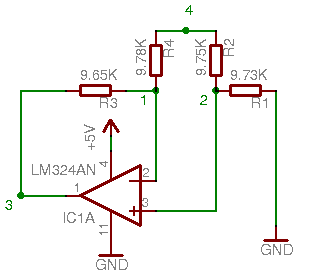
This is driving me crazy. To the left (click the image for a bigger version), you can see a basic differential amplifier based on a LM324AN op amp. If the op amp is perfect and the resistors are be exactly 10 kΩ, the potential Vout (on point 3) would be equal to the difference of potential between V+ and V- (on points 2 and 1, respectively). In other words, Vout = V+ - V-.
When working with a real op amp, the things are not that simple, but they
should remain quite close to the ideal case. In fact, if we set V4
to GND, we get reasonnable values. However, if we se V4 to
+5.05V (which is also the positive supply of the op amp), the values don't
make sense to me anymore.
Here's what I measured (the millivolt values are at least ±0.1 mV, but the volt values should be reasonnably accurate):
| V4 set to | 0 V | +5.05 V |
|---|---|---|
| V- = | 1.3 mV | 2.83 V |
| V+ = | 0.1 mV | 2.51 V |
| Vout = | 1.9 mV | 0.65 V |
When V4 is set to 0 V, the values of V- and V+ seem to be consistent with the specs of the chip regarding input offset current and input bias current (input current of 100 nA accross a 10 kΩ resistor is 1 mV).
When V4 is set to 5.05 V however, I really don't understand what laws of physics makes the difference between V+ and V- so large (0.32 V, which just happens to be half of Vout. But that's maybe just a coincidence). Further experiments have shown that Vout remains constant at 0.65 V when 2.7 V < V4 < 5.05 V, but decreases when V4 < 2.7 V.
The goal of the device is to measure the voltage across a 0.05 Ω shunt which would be placed at point 4, with 5 V applied on its R4 side and the load (a low-power electric motor) between the shunt's R2 side and the ground.
Any comment on the subject will be appreciated.
[ Posté le 16 juin 2011 à 09:42 | 1 commentaire | lien permanent ]