Battery Capacity Meter
Käännös: [ Google ]
Kategoriat: [ Tiede ]
I have over forty Ni-MH low self-discharge rechargeable batteries (mostly Eneloops, and a few Vartas and GPs) and I have noticed that some of them tend to not keep the charge very well. In order to find out which ones are worth throwing away to be recycled, I needed a device that would measure their capacity.
The principle is very simple: recharge the battery, discharge it through a resistor with a known value, measure the current while it discharges, and integrate the current over time. This will give you the battery's capacity. A few things need to be taken into account: how do you know that a battery is depleted and what discharge current should be used? From what I could gather by reading a few Web forums, the battery is considered to be depleted when its voltage goes below 1.0 V or 0.9 V (I settled on 1.0 V), and the current should be such that the battery discharges in about five hours (for a 2000 mAh battery, that would be about 400 mA). If the current is too high, the battery's voltage while it is discharging will be very close to 1.0 V already at the beginning of the process and the capacity measurement will probably be biased. I noticed this in the first iteration of the device where I had a 1 Ω resistor and a 1 A current, and decided to change for a 3.3 Ω resistor after reading about the “discharge in 5 hours” rule.
The device
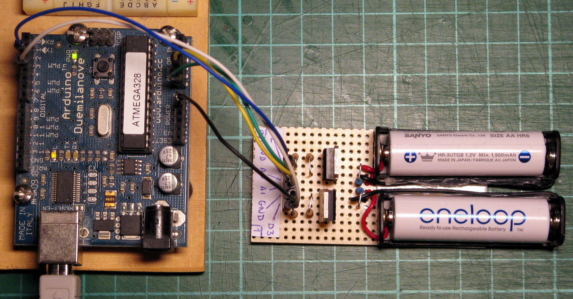
The prototype I built is very simple. The battery discharges through a 3.3 Ω ±1% 0.6 W resistor, and the voltage is measured using the Arduino's ADC (more on that below). A MOSFET (STMicroelectronics VNP35NV04-E, quite expensive but it turns fully On with only 2.5 VGS and its On resistance is only 13 mΩ, which is below the tolerance of the main resistor and the accuracy of what the Arduino can measure, so it can simply be ignored) controls the discharge and cuts the current once the “depleted” threshold has been reached to prevent damaging the battery. A 10 kΩ resistor acts as a pull-down for the MOSFET's gate, and a 110 Ω limits the gate current (whether it's really needed or not seems to depend whom you ask on Web forums, but since I had some lying around I decided to use them). There are two instances of the circuit on the prototype board, so I can test two batteries in parallel.
Accuracy of the Arduino's ADC
The Arduino's ADC has a maximum precision of 10 bits, meaning that the value read from e.g., A0 is translated to a value between 0 and 1023 included, by comparing A0 to a reference voltage that by default is the Arduino's supply voltage. It is however possible to get (reasonably) accurate voltage measurement with the Arduino (see this Web post titled Secret Arduino Voltmeter) by measuring first the supply voltage accurately against the ATMega328's internal band-gap reference. To do so, you need to first measure the band-gap reference's correct value (it's about 1.1 V, it's very stable over time and temperature, but it's exact value differs from one ATMega328 to the next).
The process therefore goes like this.
- With a trusted voltmeter, measure the Arduino's supply voltage VCC as accurately as possible.
- Using the code snippet in the blog post, measure the band-gap's value with the ADC; that gives you a number Nref. For better accuracy, compute the arithmetic mean of 1000 measurements to get rid of the random fluctuations in the measurement.
- Calculate Vref = Nref × Vcc / 1024 (and not 1023 as stated in the blog post). In my case, Vref = 1.089 V ±0.001V.
- Hardcode the Vref you have found in your Arduino program.
Then when you want to actually measure a voltage V with the Arduino's ADC, do as follows.
- Measure Nref with the ADC and compute the value of Vcc = Vref × 1024 / Nref (again, take the average of 1000 measurements).
- Measure N with the ADC and compute the value V = N × Vcc / 1024 (once again, average over 1000 measurements).
If my uncertainty calculations are correct, I get a 0.12% uncertainty on the value of Vcc (compounding the uncertainty of the voltmeter and the ADC), which is less than the 1% uncertainty on the discharge resistor value. I tried to accurately measure the 3.3 Ω resistor value, but my amperemeter is not accurate enough for currents above 200 mA, so that's the best I can hope to achieve.
Take a look at the code if you want to know the details of the implementation (especially computing in millivolts in order to use only integers instead of floats).
What about those batteries, then?
I measured the capacity of 27 batteries so far: 2 GPs, 3 Vartas and 22 Eneloops (6 of generation 1, 7 of generation 2, 2 of generation 3 and 7 of generation 4). All have a nominal capacity of 1900 mAh.
Both GPs have a capacity of 1 mAh, so they are useful only as paperweights. The Vartas have capacities of 870, 450 and 250 mAh, so they are only marginally more useful than the GPs.
One Eneloop is in really bad shape (200 mAh), but the others have capacities between 1660 and 1900 mAh, with a mean of 1790 mAh.
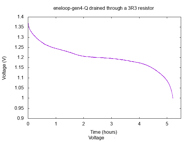
This is a typical battery, in good shape (1890 mAh). The voltage quickly drops to around 1.2 V and remains stable for a while before dropping again.

This one is definitely good for nothing (200 mAh). I remember accidentally dropping batteries on the floor a couple of times in the past, maybe this one suffered from it?
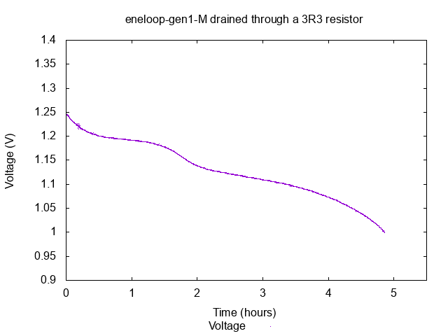
This one is a first generation eneloop, bought probably around 2011. It still has a capacity of 1660 mAh, but the shape of the curve is different from the typical one, maybe due to old age?
[ Postattu 14. joulukuuta 2019 klo 17.08 | ei kommenttia | kestävä linkki ]