Microblog : A very long article Wikipedia article on the orientation of toilet paper [7 jun à 22:52] [R]

Samedi, 24 mars 2012

Task-Based JeeNode Communication

Traduction: [ Google | Babelfish ]

Catégories : [ Bricolage/Arduino | Informatique ]

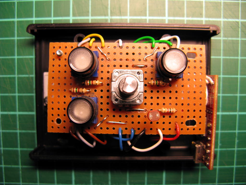
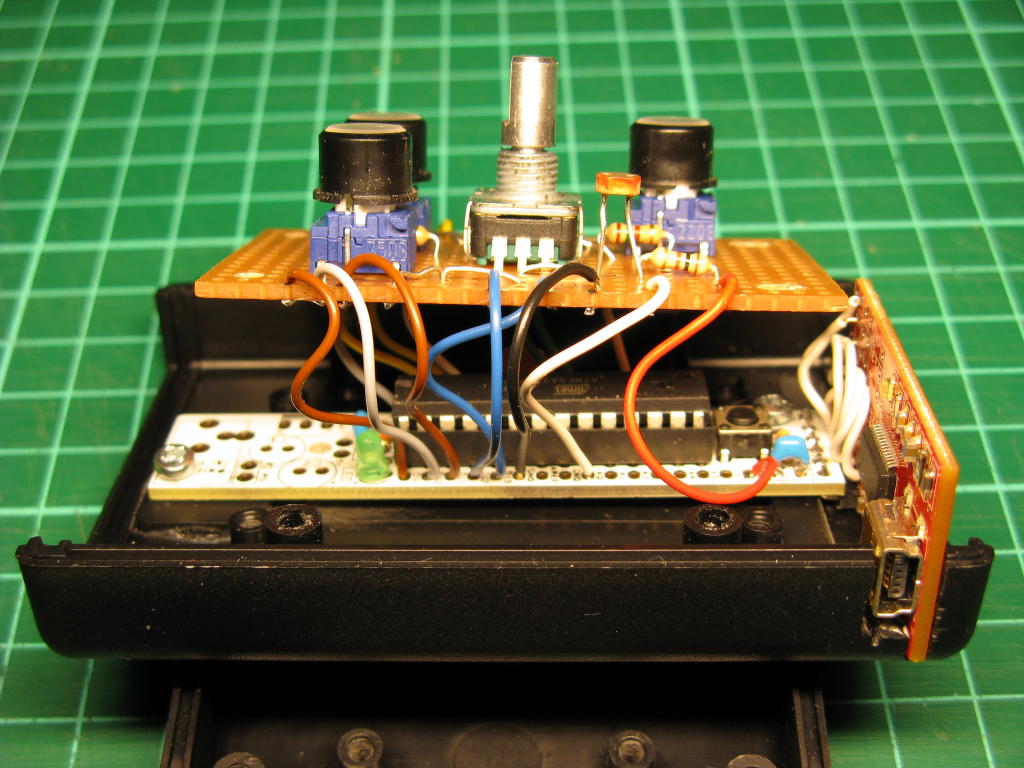
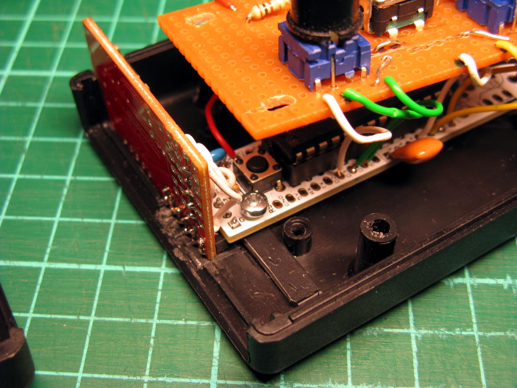
For my car heater controller I decided to use Alan Burlison's scheduler. I like it, because it leaves the main program file reasonnably short and allows to separate the code into multiple objects. I don't know if it makes the software more or less easy to write/maintain, but I find it fun to do it this way, and that's all that counts.

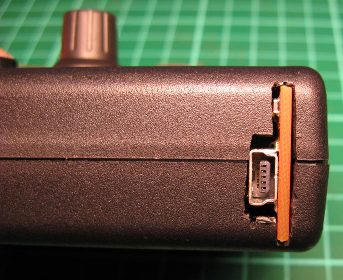
To implement 2-way communication between the JeeLink (master) and the JeeNode (slave) using Jean-Claude Wippler's RF12 library, I created a Listener object and a Speaker object that deal with receiving data and sending data respectively, while the Protocol object implements the higher-level protocol.

Here' how the slave's .pde file looks like. Notice how it contains only definitions and a bit of initialization, but no big mess of code?

#define NB_ELEMENTS(a) sizeof(a) / sizeof(a[0])
 
Speaker speaker;
Protocol protocol(&speaker);
Listener listener(&protocol);
 
Task * tasks[] = { &listener, &speaker };
TaskScheduler scheduler(tasks, NB_ELEMENTS(tasks));
 
void setup() {
  rf12_initialize(SLAVE_ID, RF12_868MHZ, HEATER_GROUP);
}
 
void loop() {
  scheduler.run(); // infinite loop
}
Here's a sample of the slave's Listener.
class Listener: public Task { // Task from Alan Burlison's scheduler
    public:
    Listener(Protocol * protocol):
      protocol(protocol)
      {};
 
    bool canRun(uint32_t now); // Taks's interface
    void run(uint32_t now);    // Task's interface
 
  private:
    Protocol * protocol;    // higher-level protocol handler
    uint8_t recv_buffer[BUFFER_LEN];
    uint8_t recv_buffer_len;
};
 
bool Listener::canRun(uint32_t now) {
  if (rf12_recvDone())
    return (rf12_crc == 0 &&  rf12_len <= BUFFER_LEN);
  return false;
}
 
void Listener::run(uint32_t now) {
  recv_buffer_len = rf12_len;
  memcpy((void *)recv_buffer, (void *)rf12_data, recv_buffer_len);
  if (rf12_hdr == (RF12_HDR_CTL | (MASTER_ID & RF12_HDR_MASK)))
    protocol->got_ack();
  else {
    if (RF12_WANTS_ACK) {
      rf12_sendStart(RF12_ACK_REPLY, 0, 0);
      rf12_sendWait(0);
    }
    protocol->handle(recv_buffer, recv_buffer_len);
  }
}

And there's the slave's Speaker. Note that the Spaker tries to send data only if its buffer_len is greater than zero. This prevents calling rf12_canSend() when it's not necessary (according to the RF12 driver, you must not call rf12_canSend() only if you intend to send data immediately after calling it). When the Protocol wants to send something, it needs to get the Speaker's buffer with get_buffer(), fill the buffer with data, and then call send(). Also, I implemented a retry mechanism in case no ACK has been received from the master.

class Speaker: public Task { // Task from Alan Burlison's scheduler
  public:
    Speaker();
    uint8_t* get_buffer();
    void send(uint8_t len, bool ack);
    void got_ack(); // called by the Protocol when it gets an ACK
    bool canRun(uint32_t now);  // Task interface
    void run(uint32_t now);     // Task interface
 
  private:
    uint8_t buffer[BUFFER_LEN];
    uint8_t buffer_len;
    bool with_ack;
    uint8_t retry_count;
    unsigned long next_retry_millis;
};
 
bool Speaker::canRun(uint32_t now) {
  if (buffer_len > 0 && retry_count > 0
                     && millis() > next_retry_millis)
    return rf12_canSend();
  return false;
}
 
void Speaker::run(uint32_t now) {
  if (with_ack && retry_count == 1) {
    buffer_len = 0;
  }
  uint8_t header = (with_ack ? RF12_HDR_ACK : 0)
                  | RF12_HDR_DST | MASTER_ID;
  rf12_sendStart(header, buffer, buffer_len);
  rf12_sendWait(0);
  if (with_ack) {
    retry_count  – ;
    next_retry_millis = millis() + SEND_RETRY_TIMEOUT;
  }
  else
    buffer_len = 0;
}
 
void Speaker::send(uint8_t len, bool ack) {
  with_ack = ack;
  buffer_len = len;
  retry_count = SEND_RETRY_COUNT + 1;
  next_retry_millis = millis();
}
 
void Speaker::got_ack() {
  buffer_len = 0;
}

The master's code is very similar, you can check it there.

[ Posté le 24 mars 2012 à 16:17 | pas de commentaire | ]

Jeudi, 22 mars 2012

Car Heater Controller

Traduction: [ Google | Babelfish ]

Catégories : [ Bricolage/Arduino ]

heater_controller_2

Finnish winters are cold, and petrol engines don't like starting when it's very cold. That's why cars are often equipped with an electric heater that preheat's the cooling liquid for some time before starting the engine. The duration of this pre-heating depends on the temperature (in French). Moreover, since I don't leave home every morning at the same time, I don't want to start heating the car at the same time every day, even if the outside temperature doesn't change much from day to day. Hence this project of a remote-controlled switch for the car heater.

The system is composed of two Arduino-compatible parts: one master, connected to the home computer (always on), and one slave, in the garage. The master is a JeeLink and the slave is based on a JeeNode. Master and slave communicate with each other with a radio (868 MHz, a free Low-power_communication_device band in Europe).

The master

Not much to say about the master, the hardware is a standard JeeLink, which for the purpose of this project is really only a radio transceiver on a Serial-over-USB interface.

The slave

heater_controller_1

The electronic is very simple, and only a few components are needed. I paid special attention to selecting components that are specified to work from -40 °C (although I have no idea how well the device works at that temperature).

The slave is organised around a JeeNode (vertical, in the right-hand corner of the picture), and has the following three features.

It controls a relay (the black box above the orange PCB on the picture), which can be open or closed.

It measures the outside temperature with a DS18S20 sensor.

It measures the current flowing out of the relay using a current transformer (the black ring aroung the brown wire on the left side of the picture).

Moreover, it has a power supply (the black box on the lower left corner of the picture).

You can also notice that the mains cable (a 5 m, outdoors prolongation cord) has an earth wire that has not been severed. The live (brown) and neutral (blue) wires have been cut and connected to the relay. Power for the power supply is taken from the plug-side of the cable, before the relay (so it's always connected to the mains).

Power supply

The power comes from a compact switching power supply that converts 230 V AC into 12 V DC (maximum output power: 4 W). In case the power supply fails, the 1 A fuse (in the holder on the big red wire on the lower-left corner of the picture) should blow before the whole thing catches on fire. Also, although the power supply is designed to be placed on a PCB, I decided not to have any 230 VAC on the PCB, so I soldered the wires straight to its input pins, and isolated them with heat-shrink tube and added epoxy for strenght (the pins are not so strong, I don't want to break them once they are connected to the thick and not-so-flexible wires).

The relay requires 12 V, hence the output value for the power supply. The JeeNode requires a 3.3 V supply, and the onboard voltage regulator could take the 12 V, but would ouput only a low current (less than 100 mA). By adding a 5 V regulator (7805) to supply the JeeNode, the latter can get more current from its on-board regulator.

Relay

The relay (specified to switch up to 400 VAC and 30 A) requires 160 mA to be activated. It is therefore controlled via a BC337 transistor, which is strong enough to withstand the current. The base of the transistor is connected to one digital pin of the JeeNode via a 2 kΩ resistor, which allows to open or close the relay by applying a High or Low signal to that pin.

Temperature sensor
heater_controller_temperature_sensor

The DS18S20 transmits the temperture information digitally over a 1-Wire bus, and therefore requires really nothing more than a 4.7 kΩ pull-up resistor. It works quite happily with 3.3 V at the end of a 15 m cable (an old phone extension cord). Note that since I have three wires in the cable, I didn't even try to power the sensor with parasitic power (anyway, I read somewhere that it doesn't work well at 3.3 V). The Arduino OneWire library does all the work for you, all you need is to connect the data pin of the sensor to one digital input of the JeeNode.

Current sensor

Finally, the current transformer is placed around the live wire coming out of the relay. The design is based on a page at OpenEnergyMonitor that does not appear to exist anymore, but this one should give a good start.

Basically, the current transformer produces a current (not a voltage) that is proportional (depending on the number of turns, my transformer has 1012 turns) to the current flowing through the mains wire that goes through the transformer. A burden resistor (68 Ω in my case) across the two wires produces an AC voltage that is proportional to this current and varies between -1.65 and +1.65 V (corresponding to mains current between -23 and +23 A peak-to-peak). Then one wire of the transformer is connected to a voltage divider made of two 20 kΩ resistors (with a filtering 47 μF capacitor) and the other wire goes to one of the analog inputs of the JeeNode. This way, the analog input sees a voltage that varies between 0 and 3.3 V, which is within the tolerance of the device.

After that, the software samples the analog value 3000 times, applies a high-pass filter to remove the DC offset, and simple math computes the RMS current. After a bit of calibration (using a 60 W lamp, and 500 W halogen lamp, a 1400 W flat iron and a 2300 W electric kettle, and comparing my measurments against those of a wattmeter), I noticed that the reported current is quite accurate (to about 0.01 A, which is more than enough for my purposes).

Box
heater_controller_in_box

The PCB and the relay a screwed on a piece of plexiglas, and the whole device is placed in a project box to protect it from dust. Zip ties around the cables near the holes prevent the cables from being accidentally pulled out of the box.

Schematics
heater_controller

The schematics are available as a PNG picture, and in Eagle format. Note that since I used strip board to assemble the circuit, I haven't paid attention to choosing the right component packages, nor the right type of component. The Eagle schematics is therefore provided for information purposes only, generating a board from it is not going to produce correct results.

The Software

It's all available there. You can obtain it with git using the command
git clone http://weber.fi.eu.org/software/arduino/heater_controller/.git/

[ Posté le 22 mars 2012 à 23:23 | 1 commentaire | ]

Jeudi, 15 mars 2012

Very big, very small

Traduction: [ Google | Babelfish ]

Catégories : [ Science ]

Scaling the solar system down to human sizes leads to more interesting comparisons. Let's assume the Earth is the size of a pin head (2 mm in diameter). We then have the following results:

  • A human being living on the surface of the pinhead would be 0.30 nm (the size of two dihydrogen molecules)
  • Mount Everest would be 1.4 μm tall (1/5 of the thickness of a strand of spider's web silk)
  • Geostationary satellites would orbit the pin head at 5 mm from its surface but the International Space Station would be at only 60 μm from the surface (the thickness of a hair)
  • A lightyear would be 1500 km long (the distance between Copenhagen, Denmark and Rome, Italy), so the closest star (Proxima Centauri) would be 6600 km away (distance between Paris, France and New Dehli, India, or between New York, USA and Berlin, Germany)
  • The Oort cloud would be 3000 km in diameter (the distance between Madrid, Spain and Helsinki, Finland, with the volley ball representing the Sun located somewhere near Cologne, Germany)
  • The diameter of the Milky Way (our galaxy) would be equivalent to the distance between the Sun and Earth
  • The whole universe would be 20·1012 km in diameter, that is 2 lightyears (diameter of the Oort cloud, or half the distance to Proxima Centauri)

[ Posté le 15 mars 2012 à 10:06 | pas de commentaire | ]

Mercredi, 14 mars 2012

The Solar system is big!

Traduction: [ Google | Babelfish ]

Catégories : [ Science ]

http://www.aerospaceweb.org/question/astronomy/q0247.shtml

Aerospaceweb.org

The solar system is big, that's well known. But how big, exactly?

Let's assume the Sun is the size of a volleyball (about 21 cm in diameter). We would then have the following relative planet sizes and distances to the ball:

  • Mercury: 1 mm diameter (a small pin head), 9 m from the ball (a bus)
  • Venus: 2 mm diameter (a pin head), 16 m from the ball (a semi-trailer truck)
  • Earth: 2 mm diameter (a pin head), 23 m from the ball
  • Mars: 1 mm diameter (a small pin head), 35 m from the ball (a blue whale)
  • Jupiter: 22 mm diameter (a walnut), 120 m from the ball (maximum length of a football/soccer field)
  • Saturn: 19 mm diameter (a smaller walnut), 220 m from the ball (one TGV train)
  • Uranus: 8 mm diameter (a cherry's kernel), 460 m from the ball (a double TGV train)
  • Neptune: 8 mm diameter (a cherry's kernel), 700 m from the ball (length of the Avenue de l'opéra, Paris, France)

By comparison, the Moon would be 0.5 mm in diameter (a grain of sand) and 6 cm from the pin head (the length of the little finger).

[ Posté le 14 mars 2012 à 23:20 | pas de commentaire | ]

Vendredi, 9 mars 2012

Large Numbers

Traduction: [ Google | Babelfish ]

Catégories : [ Science ]

Googolplex

My daughter asked me yesterday what is the largest number I know. The answer was “a Googolplex”, which is 10googol with googol = 10100.

While you can write a googol on a sheet of paper (it's a one followed by 100 zeros), you cannot write a googolplex on paper. Or can you? how much paper do you need for that?

Let's assume you can write 10 000 digits on one sheet of A4 paper. You therefore need 1096 sheets of paper. One tree can produce 10 000 sheets of paper, and there are about 1012 trees on Earth. You'd need 1080 Earths to provide all the paper. Not going to work.

Now let's see if there's even enough matter in the universe to make all this paper: assuming that all the matter in the universe can be converted to paper, is there enough of it? Paper is made of cellulose, chains of D-glucose, the latter weighing 128 g/mol. So a 5 g sheet of A4 paper contains about 2.5·1022 molecules of linked D-glucose, each of which is made of 128 hadrons (protons and neutrons). A sheet of paper is therefore made of 3·1024 hadrons, which is almos the same thing as an atom of hydrogen. The universe contains roughly 1080 atoms, which translate roughly as 1056 sheets of paper. We'd need 1040 universes to make all the needed paper. Not going to work either.

That was a very big number.

[ Posté le 9 mars 2012 à 11:44 | 1 commentaire | ]

Lundi, 13 février 2012

Git Status in Shell Prompt

Traduction: [ Google | Babelfish ]

Catégories : [ Informatique/Git ]

I thought it would be very convenient to see from the shell's prompt what branch I am currently working on. Of course, someone had got that idea well before me, and I found this implementation and this variant (the second adds space between the name of the branch and the symbols indicating the state of the branch relative to the remote branch it is tracking).

[ Posté le 13 février 2012 à 15:30 | pas de commentaire | ]

Jeudi, 9 février 2012

Stripboard Sketch Paper

Traduction: [ Google | Babelfish ]

Catégories : [ Bricolage ]

proto_board_sketch

I don't like to start soldering on a stripboard without having sketched the positions of the different components beforehand on a paper. While this is easily done on the back of an envelope, having 1:1 scale sketchpaper would be handy. So I made such a printable sketchpaper.

[ Posté le 9 février 2012 à 08:55 | pas de commentaire | ]

Mardi, 31 janvier 2012

Temperature Histogram

Traduction: [ Google | Babelfish ]

Catégories : [ Science ]

temperature_jkl_10_years_frequency

I have collected slightly over 10 years worth of hourly tempertature readings in Jyväskylä. The sources of temperature over the years have been the University of Jyväskylä's weather station, the METAR data for Jyväskylä's airport and the Finnish meteorological service which is currently being used; these services together were on average available 98.7% of the time.

The other day I wondered what a histogram of those values would look like, and here it is. The numbers have been rounded to the their closest integer values, and range from -35 °C to +34 °C. One disproportionately large peak large can be observed at 0 °C, probably due to melting ice/freezing water remaing in the sensor's surface and keeping it at exactly that temperature while the air around it would be slightly different (if you have a better explanation, don't hesitate to leave a comment!). Surprisingly, there is a second peak at 13 °C (explanations are welcome too!).

Finally, the average temperature is 4.0 °C, which is consistent wit the average minima (-1.4 °C) and maxima (7 °C) values given on Wikipedia's article about Jyväskylä.

[ Posté le 31 janvier 2012 à 22:54 | pas de commentaire | ]

Jeudi, 5 janvier 2012

Circuit auto Noël 2011

Catégories : [ Jeux ]

circuit_auto_noel_2011

Pas de circuit auto l'été passé, mais j'en ai monté un pendant ces vacances. Composé essentiellement de virages, j'ai réussi à en faire le tour en (un peu) moins de 4 secondes.

[ Posté le 5 janvier 2012 à 19:46 | pas de commentaire | ]

Mercredi, 28 décembre 2011

Timelapse Controler

Traduction: [ Google | Babelfish ]

Catégories : [ Bricolage/Arduino ]

timelapse_controller

The timelapse photography controller I helped a friend build is finally complete. He built the hardware, I wrote the software. The latter is uselessly complicated, but I wanted to have fun with C++ and multiple inheritance, so here it is. The device is controlled by a rotary encoder with an integrated push button and a 2x16 character LCD display. It also has a plug to connect it to the camera (via a 2-channel optocoupler) and is powered with 4 AA batteries.

The UI is composed of 4 screens:

  • a status screen, showing how many pictures have been taken so far, as well as the voltage of the batteries
  • a start/stop screen
  • a screen for setting the number of pictures
  • a screen for setting the time interval between the pictures.

Turning the knob moves from one screen to the other, while pressing its button activates the current screen (e.g., starting or stopping, or allowing to change the value of e.g., the time interval).

The last two screens are disabled when the timer is started, and re-enabled when it is stopped. Also, the screen is turned off after a 10s timeout, and switched back on when the button is pressed or the knob is rotated. This allows to reduce the power consumption from abuot 24 mA to 8 mA. This way, a set of 2000 mAh rechargeable batteries should last over 200 hours.

[ Posté le 28 décembre 2011 à 20:40 | pas de commentaire | ]

Vendredi, 2 décembre 2011

Don't Forget pinMode()

Traduction: [ Google | Babelfish ]

Catégories : [ Bricolage/Arduino ]

I spent hours with a friend trying to solve the following problem: an LED and a 430R resistor are connected to the pin of an Arduino (actually an RBBB powered with 3.3 V). Using digitalWrite(pin, HIGH) it did light the LED, but it was very dim. What was more weird, is that the pin was showing only 1 V instead of 3.3 V. After two hours of scratching our heads, I looked up on Google and found the answer: “don't forget to call pinMode(pin, OUTPUT)…”

At boot time, the pins are set as inputs. digitalWrite(pin, HIGH) switches the internal pullup resistor (20K – 50K), which is enough to allows the pin to source a little bit of current at a quite low voltage. It was enough the dimly light the LED, but not enough to get the optocoupler (that was initially connected to the pin) to work properly.

[ Posté le 2 décembre 2011 à 16:38 | pas de commentaire | ]

Vendredi, 11 novembre 2011

Traffic Shaping

Traduction: [ Google | Babelfish ]

Catégories : [ Informatique ]

I have an asymetrical ADSL connecion (1024 kbps downstream, 512 kbps upstream) and when I'm downloading a large file, SSH connections become unresponsive. After a bit of reading, I found one traffic shaping script that allows to keep responsive interactive SSH connections, at the cost of a slightly limited download speed. The explanations are from the Linux advanced routing and traffic control howto, in the cookbook chapter.

The explanations goes like this:

“ISPs know that they are benchmarked solely on how fast people can download. Besides available bandwidth, download speed is influenced heavily by packet loss, which seriously hampers TCP/IP performance. Large queues can help prevent packet loss, and speed up downloads. So ISPs configure large queues.

These large queues however damage interactivity. A keystroke must first travel the upstream queue, which may be seconds (!) long and go to your remote host. It is then displayed, which leads to a packet coming back, which must then traverse the downstream queue, located at your ISP, before it appears on your screen.

This HOWTO teaches you how to mangle and process the queue in many ways, but sadly, not all queues are accessible to us. The queue over at the ISP is completely off-limits, whereas the upstream queue probably lives inside your cable modem or DSL device. You may or may not be able to configure it. Most probably not.

So, what next? As we can't control either of those queues, they must be eliminated, and moved to your Linux router. Luckily this is possible.

Limit upload speed By limiting our upload speed to slightly less than the truly available rate, no queues are built up in our modem. The queue is now moved to Linux.

Limit download speed This is slightly trickier as we can't really influence how fast the internet ships us data. We can however drop packets that are coming in too fast, which causes TCP/IP to slow down to just the rate we want. Because we don't want to drop traffic unnecessarily, we configure a 'burst' size we allow at higher speed.”

It really does wonders, on the condition that you set the DOWNLINK speed to 800 kbps (80% of my downlink) and the UPLINK to 440 kbps (85% of my uplink). I tried with 900 kpbs instead of 800, and it didn't work. One day, I will take the time to think about the why, but for now I'm just happy that it works properly.

Next step: try to get this to work on the ADSL modem/router (luckily running linux and accessible with ssh) instead of the desktop.

[ Posté le 11 novembre 2011 à 22:09 | pas de commentaire | ]

Mercredi, 2 novembre 2011

Git in a (Very Small) Nutshell

Traduction: [ Google | Babelfish ]

Catégories : [ Informatique/Git ]

When I started to use git and read the man pages, I was sorely missing a brief description of how Git's features and concepts relate. Now that I finally understand (at least, I think) how Git works, I wrote this document. It's not a tutorial (the existing ones are good enough that I don't need to write another one), but rather a summary of how Git's main features relate to the jargon used in the man pages.

Saving your changes

Let's say you have a set of files in your working tree. Git works by saving a full copy (snapshot) of this set; this is called a commit. When you want to make a new commit using Git, you first need to tell Git which files are going to be part of this commit. You do this with the git add my_file command. The files are then added to the index, which is the list of files that are going to compose the commit. You then run git commit, which creates a new commit based on the files listed in the index. You are also prompted for a message that describes the commit. The message is structured with a heading (the first line of the message) separated by an empty line, from the body of the message. Lines starting with a hash symbol are comments and are not recorded into the message.

Adding a new file to the index and creating a commit containing this file has the side effect of letting Git track this file. If you want to create a commit composed of all the tracked files, you can run git commit -a, which implicitely adds all the tracked files to the index before creating a new commit.

A commit is identified by a SHA1 hash of its content, e.g, cdf18108b03386e1b755c1f3a3feaa30f9529390. Any non-ambiguous prefix of that hash can be used as a commit ID e.g., cdf1810.

The add/commit mechanism allows to split a set of changes into multiple commits (you create a commit for a subset of your files, then you create another commit for the rest of your files).

Creating a new repository

For a new project

The command git init creates a repository in the current directory (a .git directory that holds all the data necessary for Git to work). You can then add the files you need to have under version control (using git add, wildcards such as '*' are accepted) and create the initial commit with git commit.

Copying an existing repository

To copy an existing repository, use the git clone command. Most services that offer source code as Git repositories indicate the necessary Git command line to run.

Finding a commit

To view a summary of the changes that have happened in the repository, you can use git log; the top of the list is the most recent commit. To view the succession of changes (as diffs) that were made, use git log -p.

Git does its best not to lose anything you have recorded. The command git reflog shows a log of how the tip of branches have been updated, even if you have done acrobatic things.

Branches

When you make changes to your working tree and create a new commit, Git links the new commit to the commit that represents the state of the working directory before the changes (called in this context the parent of the new commit). The chain composed of the new commit, its parent, its parent's parent and so on, is called a branch. The name of the default branch is “master”. The most recent commit in a branch is called its HEAD.

A branch is nothing more than a name and the commit identifier of its tip; this is called a ref. For example refs/heads/master is the ref for the master branch. Finding the commits that compose the branch is a simple matter of following the tip's parent, and the parent's parent, and so on.

If you can decide to fork your work at some point, create a new branch by running git branch new_branch. This command creates the branch, but does not switch to that branch (changes and commits will still be appended to the current branch). To effectively change branch, you need to checkout the HEAD of the new branch by running git checkout new_branch. From this point on, changes and commits will be appended to the new branch.

Merging

If at some point it is necessary to merge the content of e.g., the new branch into the “master” branch, you need to checkout “master” and then run git merge new_branch.

If Git doesn't know how to merge two branches, it complains about conflicts and lets the user edit the incriminated files by hand. This is done by choosing, in sections of these files indicated with <<<<<< and >>>>>>> markers, which variant is to be retained. Once the editing has been made, the changes need to be committed (with git commit -a).

Checking out

You can checkout any commit with git checkout and thus have your working directory reflect the state of the repository at any point in time. When you do that, you are not on any branch anymore, which will cause various warning messages (such as “You are in 'detached HEAD' state”) and cause Git to behave in a way you may not expect (that is, if you don't understand properly yet how Git works). To go back to a “normal” situation, just run git branch master (or any other branch that exists). To prevent going into detached HEAD state, use git checkout -b new_branch to create a new branch that starts at <commit>.

If you have made local changes, Git won't let you checkout another branch. You must either commit them or reset the working tree before being allowed to do the checkout.

Reset

The command git reset allows to do multiple things. One of its most common use (git reset --hard) is to cancel all changes you have made to the working tree since the last commit.

If you specify a commit ID after git reset, it will move the HEAD of the current branch back to that commit, which becomes the new HEAD; all commits after this point are removed from the branch (but not from the repository! You can always restore the old HEAD by finding its commit ID with git reflog).

Working with remote repositories

Pull (and Fetch)

Some time after you have cloned a public repository, you may want to update your local copy so that it mathtches the latest version available at the original repository. This update is done with with git pull. When the repository was cloned, Git had created a remote (a link to the source repository) called by default “origin”. Below the hood, git pull calls git fetch to retrieve the commits from all the relevant branches on “origin”, and then calls git merge to merge those changes with the local current branch.

Note that refs/remotes/origin/master is the ref to the master branch at “origin”, but it is actually a branch stored locally that reflects the “master” branch on the “origin” repository. This kind of ref is used for specifying what remote branch is tracked by what local branch when using git fetch. Typically, +refs/heads/:refs/remotes/origin/ indicates that e.g., the local branch “master” tracks the remote branch “origin/master” (“*” represents a wildcard).

Push

If you have writing permissions on the remote repository, you can send your changes using git push (it defaults to the “origin” remote). Note that the HEAD of the branch to which you push changes must be the parent of your changes. If this is not the case, the push will fail and you will be asked to first pull from the remote repository to get the latest version, fix potential conflicts and only then push your changes.

It is also important to remember that you cannot normally push to a repository that has a working tree. The remote repository must have been created with the git init --bare command.

[ Posté le 2 novembre 2011 à 08:36 | pas de commentaire | ]

Dimanche, 23 octobre 2011

Git Recipes

Traduction: [ Google | Babelfish ]

Catégories : [ Informatique/Git ]

Here are a few recipes I use with git.

Using git log

Show which files have been modified by the commits: git log --name-status

View the successive changes for a given file: git log -p -- my_file (latest change first)

View the changes at word-level instead of line-level: git log --color-words

Make --color-words more readable with LaTeX files: add *.tex diff=tex to the repository's .git/info/attributes or to your $HOME/.gitattributes (read man gitattributes for more info on this, it supports other languages too)

Browseable Web Repository

To make an online, browsable web repository on a web server (I assume you have ssh access to it).

On the server, run:
$ mkdir some_directory
$ cd some_directory
$ git init
$ git config receive.denyCurrentBranch ignore
$ cat > .git/hooks/post-receive <<EOF
#!/bin/sh
GIT_WORK_TREE=.. git checkout -f
GIT_WORK_TREE=.. git update-server-info --force
EOF
$ chmod a+x .git/hooks/post-receive
The in the source repository, run:
$ git remote add web username@my.web.server:path/to/some_directory/.git
$ git push web master

(“username”, “my.web.server” and “path/to/” are exactly what you think they are.) Note the “.git” at the end of the path, it has to be there because git push is going to send its data into that directory.

When you run git push web master to upload the content of the source repository to the web repository, the post-receive hook checks out the latest version. The next time, you don't need to specify the “master” branch any more, simply running git push web is enough.

[ Posté le 23 octobre 2011 à 15:57 | pas de commentaire | ]

Mercredi, 12 octobre 2011

Autofs

Traduction: [ Google | Babelfish ]

Catégories : [ Informatique ]

Autofs allows to automatically mount a filesystem when changing directory to the mounting point. The process is frozen while the file system is being mounted, and then the chdir() completes and enters the root of newly mounted filesystem.

I have been using autofs for several years, at first for mounting USB sticks, but now also for SMB shares and SSHFS. It is meant to be used for command-line users, I don't doubt that modern desktop environments provide the same features for GUI users.

The following describes my setup on a Debian Squeeze; there may be a more modern way of doing things (the original setup was on a Debian Sarge). I assume that you know how to administrate a Debian system (in other words, I won't be held responsible for damaging your system if you follow those instructions without understanding what they mean).

Autofs

The first step is to install the autofs, bsdutils, coreutils, lockfile-progs, gawk (or mawk), sed and the util-linux packages (most of those are probably installed already). The wget package (and command) allows me to write concise commands below, but feel free to use any other tool to download the necessary files from my web page.

USB Automounter

This setup allows to mount automatically any USB Mass Storage device, without the need to manually configure anything (as is the case in this Debian tutorial).

Edit as root the /etc/auto.master and add the following line:

/media  /etc/auto.usb  --timeout=3

Then run the following as root:

# mkdir -p /media
# mkdir -p /var/run/usbautomount
# mkdir -p /etc/usbautomount
# wget -O /etc/usbautomount/usbautomount http://weber.fi.eu.org/software/autofs/usbautomount
# chmod 755 /etc/usbautomount/usbautomount
# wget -O /etc/udev/usbautomount.rules http://weber.fi.eu.org/software/autofs/usbautomount.rules
# cd /etc/udev/rules.d
# ln -s ../usbautomount.rules z60_usbautomount.rules
# /etc/init.d/autofs restart

You then need to edit /etc/usbautomount/usbautomount to change references to mweber to your own username, and possibly change the mounting options (see line 142 of the script). I still use latin1 as a character encoding, so I want filenames to be automatically translated into latin1 for VFAT filesystems. Other filesystems are mounted without particular options.

The idea here is that when you plug a USB Mass Storage device into the computer, udev runs the usbautomount script that creates a name based on the USB device's vendor, model, instance (in the case the physical device contains more than one USB Mass Storage device, such as multi-card readers or smartphones with internal and removable flash memory) and partition number, creates a symlink in /var/run/usbautomount that points to a directory of the same name in /media. When you access the symlink, automount creates the directory in /media and mounts the file system from the USB device to that directory.

If you chdir() out of that directory, after 3 seconds automount unmounts the filesystem. If you chdir() into the directory again, automount mounts it again. The short timeout for automatic unmounting allows to unplug the device almost immediately after cd-ing out of the mount point (provided that there is no data to be written onto the device anymore). When you unplug the device, a script (generated by usbautomount when the device was plugged in) is run to remove the symlink from /var/run/usbautomount.

The cherry on the cake of this setup is the following:

$ mkdir $HOME/mnt
$ ln -s /var/run/usbautomount $HOME/mnt/USB

This way, $HOME/mnt/USB is automatically populated with links to the devices that you plug to your computer.

SMB/CIFS shares

The smbclient and cifs-utils packages need to be installed.

Run as root:

# mkdir -p /mnt/smb

Edit as root the /etc/auto.master and add the following line:

/mnt/smb  /etc/auto.smb  --timeout=10

(/etc/auto.smb comes with the autofs package).

Run this as your regular user:

$ ln -s /mnt/smb $HOME/mnt/smb

If you have an SMB/CIFS server named "foo" containing shares called "bar" and "quux", then going into /mnt/smb/foo will mount "bar" and "quux" in /mnt/smb/foo/bar and /mnt/smb/foo/quux. Automatic unmounting will happen 10 seconds after leaving /mnt/smb/foo.

If "foo" requires credentials (login and password), you can put them in /etc/auto.smb.foo as follows:

username = my_username
password = my_password

SSHFS

SSHFS itself requires some amount of setup. I will assume in the following that the client computer is called "local" and it accesses using SSH and SSHFS a remote computer called "remote" with user "user".

First, install the sshfs package. Then you need to create an SSH key for root@client, and authorize this key for user@remote. In the end, root@local must be able to log into user@remote using an SSH key instead of a password.

Once this is working, run as root:

# mkdir -p /mnt/ssh

Then edit /etc/auto.master as root and add the line:

/mnt/ssh  /etc/auto.ssh  --timeout=10,--ghost

Then create /etc/auto.ssh and add a line that looks like this (change the "user", and "remote" as needed):

remote -fstype=fuse,rw,nodev,nonempty,noatime,allow_other,max_read=65536 :sshfs\#user@remote\:

By default, SSHFS will mount the home directory of "user@remote" into /mnt/ssh/remote. If you need to acces another directory (e.g., /tmp), just append this path to the end of the line in /etc/auto.ssh:

remote-tmp -fstype=fuse,rw,nodev,nonempty,noatime,allow_other,max_read=65536 :sshfs\#user@remote\:/tmp

Finally, run this as your regular user:

$ ln -s /mnt/ssh $HOME/mnt/ssh

CDROM

It just came to my mind the other day that I could automount CD and DVD as well, but I haven't thought about the details yet. I remember the feature to be very annoying in Solaris twelve years ago, where the system was mounting the CD in a directory named after the label of the CD's filesystem, and never removing this directory. After mounting a few discs, the automount directory was filled with various directories with abtruse names, and you had to guess which one contained your data (I suppose mount would have told me what I wanted to know, I don't remeber if I tried that).

[ Posté le 12 octobre 2011 à 11:49 | 3 commentaires | ]

Dimanche, 25 septembre 2011

Crumble aux poireaux

Catégories : [ Cuisine ]

Cette recette est adaptée de ce que j'ai vu dans un épisode de l'émission 30-minute meals avec Jamie Oliver. J'ai vu moins de la moitié de l'épisode, et donc je n'avais aucune idée de ce que le plat devait donner.

Ingrédients

  • 3 poireaux
  • 1 gros oignon
  • 140g de lard fumé en tranches fines
  • 3 gousses d'ail
  • 4 grosses tranches de pain
  • huile d'olive
  • thym
  • romarin
  • 100mL eau

Préparation

Faire revenir le lard coupé en morceaux, verser (avec la graisse fondue) dans un plat allant au four. Ajouter l'oignoon émincé (pas trop fin), puis couvrir avec les poireaux émincés. Verser l'eau, saupoudrer avec le thym et le romarin, et placer 20 min au four préchauffé à 200 °C. Placer le pain, les gousses d'ail non épluchées et une bonne rasade d'huile d'olive dans un mixer, et mixer jusqu'à obtenir des miettes imbibées d'huile. En saupoudrer le plat, et repasser au four 10 minutes.

Commentaires

  • J'ai servi ce plat en plus de pommes de terre roties comme accompagnement de morceaux de filets de truite saumonnée grillés à la poële.
  • Après lecture de la recette, je pense qu'il faudrait faire revenir les oignons et les poireaux avec le lard, probablement sans eau, et ne mettre au four que pour faire dorer les miettes de pain.
  • La recette d'origine est un pseudo-cassoulet, donc on rajoute de la purée de tomates et des haricots blancs dans la préparation, et on y dépose des saucisses.

[ Posté le 25 septembre 2011 à 18:10 | pas de commentaire | ]

Dimanche, 18 septembre 2011

Tréma manuel en LaTeX

Catégories : [ Informatique ]

La fonte Stork Bill ne possède pas de caractère accentué du tout. Pour fignoler le livret de règles du Decktet, il me fallait un “ä” et un “ö” pour écrire “Quäsenbö” (le titre d'un jeu). J'ai donc bricolé un tréma à la main à partir de deux points:

\makeatletter
 
\newcommand{\umlaut}[1]{%
\sbox\@tempboxa{#1}%
\@tempdima -.5\wd\@tempboxa
\@tempdimb 1.1\ht\@tempboxa
\sbox\@tempboxa{..}%
\advance\@tempdima -.5\wd\@tempboxa
#1\hskip\@tempdima\raisebox{\@tempdimb}{\usebox\@tempboxa}%
}

La commande s'utilise de cette manière:

Qu\umlaut{a}senb\umlaut{o}

Le résultat est potable pour la fonte en question, qui en tant que fonte décorative n'a pas besoin d'être parfaitement régulière, mais ne donne rien de bon avec par exemple lmodern (qui n'en a pas besoin de toutes façons puisque cette dernière contient déjà les caractères accentués idoines).

[ Posté le 18 septembre 2011 à 15:52 | pas de commentaire | ]

Jeudi, 8 septembre 2011

Autofs and CD drive

Traduction: [ Google | Babelfish ]

Catégories : [ Informatique ]

After yesterday's tutorial on Autofs, I gave some thought on using Autofs to automatically mount a CD/DVD. Here's the result (read the previous tutorial first for complete information).

Run as root:

# mkdir -p /mnt/cdrom

Then edit /etc/auto.master as root and add the line:

/mnt/cdrom  /etc/auto.cdrom  --timeout=10

Then create /etc/auto.cdrom and add a line that looks like this (change /dev/cdrom to the proper device if needed):

cd1   -fstype=iso9660,ro,nosuid,nodev :/dev/cdrom

(shamelessly copied from the supplied /etc/auto.misc). Finally, run this as your regular user:

$ ln -s /mnt/cdrom/cd1 $HOME/mnt/cdrom

This setup is a bit crooked, because autofs is designed to watch one directory (/mnt/cdrom in this case) and create different subdirectories for different devices. In this case howerver we have only one device, that we mount always to the same point. On the brighter side, if you have more than one CD/DVD/floppy/zip drive, you can rename references to cdrom as removable, and add multiple lines to /etc/auto.removable, one for each drive. See /etc/auto.misc (that file comes by default with the autofs package) for extra possibilities of configuration.

[ Posté le 8 septembre 2011 à 15:59 | pas de commentaire | ]

Jeudi, 25 août 2011

Second Page

Catégories : [ Blog ]

Les résumés et les bières n'intéressent finalement pas grand monde, donc j'ai remplacé le filtre optionnel par une « seconde page » obligatoire. Pour désactiver ce filtre, il faut ajouter ?all=1 dans l'URL. Ceci s'applique aussi aux flux RSS.

Summaries and beers are not interesting to most people, so I replaced the optional filter with a mandatory “second page”. To disable this filter, add ?all=1 to the URL. The same applies to RSS feeds.

Yhteenvedot ja oluet eivät kiinnosta useimpia lukijoita, joten korvasin vapaaehtoisen suodattimen pakollisella “toisella sivulla”. Suodattimen voi pysäyttää lisäämällä ?all=1 URL-osoitteen loppuun. Sama koskee RSS-syötteitä.

[ Posté le 25 août 2011 à 18:34 | pas de commentaire | ]

Mardi, 23 août 2011

Dieharder Test

Traduction: [ Google | Babelfish ]

Catégories : [ Informatique ]

whitenoise

It took about a week to generate a bit over 100 MB of random data with the arduino-based hardware random number generator. I used the JeeLink-based one, and the last chunk of random data (50 MB) was generated at a speed of 1562 bits/s.

And now for some statistical tests.

Fourmilab's ent test returns:

Entropy = 7.999998 bits per byte.
 
Optimum compression would reduce the size
of this 106315776 byte file by 0 percent.
 
Chi square distribution for 106315776 samples is 240.83, and randomly
would exceed this value 72.90 percent of the times.
 
Arithmetic mean value of data bytes is 127.4987 (127.5 = random).
Monte Carlo value for Pi is 3.140987091 (error 0.02 percent).
Serial correlation coefficient is 0.000165 (totally uncorrelated = 0.0).

I also ran the Dieharder test suite, which ran 40 tests on the data. Out of those, I got:

  • 34 PASSED
  • 1 POOR (1 RGB Bit Distribution Test out of 12 instances of the test)
  • 2 POSSIBLY WEAK (Diehard OPSO and Diehard Squeeze Test)
  • 3 FAILED (Diehard Sums Test and two instances of Marsaglia and Tsang GCD Test)

At the end of the series of tests, the software indicates that “The file file_input_raw was rewound 181 times”, meaning that I should get a lot more random data than 100 MB (ideally 18 GB, which means running the generator for 3.5 years) not to have the rewind the file for any of the tests.

The important question is however: 34 passed out of 40, is it good enough or not?

[ Posté le 23 août 2011 à 10:48 | 2 commentaires | ]

Jeudi, 18 août 2011

Journalisme du dimanche

Catégories : [ Râleries | Science ]

Soit une dépèche AP Un Suédois essayait de fractionner des atomes dans sa cuisine (via fr.news.yahoo.com) commençant par (le gras a été rajouté)

« Un Suédois arrêté pour avoir tenté de réaliser une fission nucléaire dans sa cuisine »

Cette dépèche, reprise par Zignonet, devient Il essayait de construire un réacteur nucléaire dans sa cuisine (via fr.news.yahoo.com encore une fois) et commence par (le gras a été rajouté)

« Un Suédois de 31 ans a été arrêté fin juillet pour avoir fait une fission nucléaire à son domicile »

On n'a pas besoin d'un doctorat en physique nucléaire pour comprendre que tenter de réaliser et faire ne signifient pas la même chose. Il faut avoir appris à lire pour comprendre la différence, certes, c'est peut-être là que le bât blesse.

Un peu plus loin, AP indique

« il avait provoqué une petite fusion sur sa cuisinière »

que Zigonet interprète comme

« il avait réussi à provoquer une fission nucléaire dans sa cuisine »

Un élève de l'école primaire est capable de reconnaître que les mots fusion et fission ne sont pas les mêmes, même s'ils n'y a que deux lettres de différence entre les deux. Tout le monde conviendra que par exemple lapin et clampin, bien que n'ayant que deux lettres de différence, ne signifient pas la même chose : l'un est un adorable rongeur aux longues oreilles, tandis que l'autre non.

Les cours de physique atomique du lycée permettent de savoir que la seule fusion nucléaire obtenue sur Terre à ce jour concerne des atomes d'hydrogène, et que si l'apprenti Oppenheimer avait obtenu une fission nucléaire, la police n'aurait retrouvé personne à arrêter (mais les problèmes de surpopulation à Stockholm auraient été promptement résolus). Avec les histoires récentes de Fukushima, tout le monde devrait cependant savoir ce qu'est la fusion du combustible nucléaire (qui n'est pas la même chose que la fusion nucléaire), c'est à dire que ce dernier, produisant naturellement de la chaleur, peut fondre sous l'effet de cette dernière. On peut donc supposer que c'est ce qui s'est passé dans cette cuisine. AJOUT en lisant le blog du bonhomme je ne suis même pas sûr qu'il se soit agit de ça. Il a fait chauffer de l'americium, du radium et du beryllium dans de l'acide sulfurique et ça a explosé, probablement sous l'effet de l'ébullition de l'acide (qui bout à 337 °C, alors que les trois premiers fondent à 1176, 700 et 1287 °C respectivement).

En conclusion, quelques mots de différence changent complètement le sens d'un texte, et ce n'est pas parce qu'on publie des trucs sur le Web qu'on est un journaliste.

[ Posté le 18 août 2011 à 17:41 | pas de commentaire | ]

A More Complicated PasswordCard!

Traduction: [ Google | Babelfish ]

Catégories : [ Informatique ]

http://webspace.ship.edu/ambart/i_brain_knot.jpg

Angela Bartoli

To protect the password card from theft, there is one possibility. First, randomly generate and memorize a secret key composed of 12 numbers between 0 and 35 (one for each line of the card). Then for each letter of the mnemonic, shift this letter to the right (looping around the end of the line back to its beginning if needed) by the amount indicated by this line's secret key's digit before reading the symbol.

For an 8-symbol mnemonic, the entropy of this secret key is 41.4 bits, which gives a reasonnable amount of protection to the card even if it is stolen.

One obvious drawback is of course the strain it puts on the brain (although some may say it's good for the organ's health to work it out this way) and the time it takes to read one password. Another drawback is that the secret key is hard to remember, and if you forget it, you loose all your passwords.

Translating the secret key into letters and digits might make it easier to remember.

[ Posté le 18 août 2011 à 17:24 | pas de commentaire | ]

Mardi, 16 août 2011

A Better PasswordCard?

Traduction: [ Google | Babelfish ]

Catégories : [ Informatique ]

pwcard

The PasswordCard sounds like a good idea (and it actually may be in practice), but I don't like it so much for three reasons:

  • The entropy is too low (64 bits spread over 232 symbols) and generated from an unknown source of entropy.
  • You have to memorize a cryptic symbol and a color for each password, which makes it easy to forget which symbol/color pair is associated with what password.
  • I didn't invent it :)

My current idea is to generate a similar card using a hardware random number generator so that each symbol on the card has an entropy of 6 bits (2592 bits in total on he card). I also would like to get rid of the method that consists in choosng one spot on the card and reading in one direction, and instead use the card as a lookup table for a substitution cipher: you choose a cleartext mnemonic for a given website with a length corresponding to the length of the password you want to generate (e.g., “EXAMPLEC” for an 8-symbol password to be used on example.com), and you generate the corresponding password by looking up the symbol corresponding to “E” on the first row of the card, then the one corresponding to “X” on the second row, “A” on the third, “M” on the fourth, and so on.

The drawbacks are numerous:

  • Reading a password this way is very slow and error-prone (the alternating gray and white areas and the repeated header lines make it only slightly less painful).
  • Generating two passwords from the same card is fine as long as the two mnemonics don't share the same characters in the same positions (e.g., “EXAMPLEC” and “EXNIHILO” share “EX” in positions 1 and 2) (if this is the case, the entropy of those particular symbols will be divided by the number of passwords sharing them).
  • The mnemonics are meant to be easy to remember, and therefore easy to guess by the thief of the card (that's howerver only slightly worse than the case of the stolen PasswordCard).
  • It requires a computer to generate a card that is readable in a small format, so the random bits are temporarily stored on a system that may be compromised (if the physical size of the card does not matter, you can generate such a card by rolling a pair of 6-sided dice about 729 times and writing the symbols down by hand).

There is one benefit though: the card looks very geeky :)

As usual, any comment/idea/criticism is welcome.

[ Posté le 16 août 2011 à 23:14 | 1 commentaire | ]

Lundi, 15 août 2011

Hardware Random Number Generator

Traduction: [ Google | Babelfish ]

Catégories : [ Bricolage/Arduino | Informatique ]

whitenoise

Software random number generators are usually so-called pseudo-random number generators, because they produce a deterministic sequence of numbers that have some of the properties of true random numbers. Obtaining genuinly random numbers howerver requires a non-deterministic processus as the source of randomness. Thermal noise in electronics or radioactive decay have been used, usually requiring an external device to be built and plugged to the computer.

Peter Knight's TrueRandom generates random bits by using the Arduino's ADC (with nothing connected to the analog input pin) to measure electronic noise. It flips the pin's internal pull-up resistor while the measure takes place to increase the amount of noise. The software then keeps only the least significant bit of the result, filters it using Von Neumann's whitening algorithm (read pairs of bits until they are of different values and return 0 (respectively 1) on a 01 (respectively 10) transition). There are several functions that generate different types of numbers based on those random bits.

I reused that code, modified it to allow using another pin than the Arduino's Analog0 and I made my own random number generator. I also wrote a Python script that reads the bits from the serial port, uses the SHA-1 hashing algorithm to distil the data (the raw data has about 6 bit of entropy per byte, distillation produces data with 7.999 bits of entropy per byte; based on the work of Jeff Connelly on IMOTP) and writes them to the standard output or into a file. On my Duemilanove, it can output about 1500 bits/s, while it outputs 1300 bits/s on a JeeLink. The latter makes it an easy-to-transport device that is reasonnably sturdy and fits in the pocket, even if its features (it contains a radio transceiver) are a bit overkill for the job (not to mention expensive).

I also adapted the core of the TrueRandom software to run on my ButtonBox (which is conveniently always connected to my desktop computer). There the output rate is a mere 300 bps, but it's still reasonnably fast for generating a few random numbers when needed (for example for generating one's own PasswordCard). The access to the ButtonBox is shared among multiple clients using button_box_server.py, so a modified Python script was used for obtaining the stream of random bits through the button_box_server.

I haven't had the patience to generate a few megabytes of random data to test the generator with the DieHarder test suite, but the output of Fourmilab's ent test tool looks reasonnable.

[ Posté le 15 août 2011 à 11:08 | 2 commentaires | ]

Vendredi, 12 août 2011

Password Management with the PasswordCard

Traduction: [ Google | Babelfish ]

Catégories : [ Informatique ]

It all started a few days ago with this Xkcd strip. Someone pointed it out passwordcard.com to me, and it made me wonder how safe are the passwords generated with that tool. Those passwords are meant to be used on all those websites that require you to create a user account with a password. Using a single password for all those web sites means that when the attacker of one of those websites gets your password, he can access your account on every other website where you have an account.

Beware that I'm no mathematician, and neither am I a specialist in cryptography or information theory, but here are my thoughts on this system.

The generator is based on what looks like a 64-bit key, so in theory, the entropy is 64 bits, which is reasonnably much (it would take 6x10⁸ years to break at 1000 attempts per second). However, since you need to feed the key to an unknown web server, the practical entropy is much less, since someone else than you knows the key. But let's assume you can generate the card yourself on a secure computer.

The symbols on the card are upper- and lower-case letters, and digits, which makes overall 62 possible combinations. This gives 5.95 bits of entropy per such symbol, if the symbol is randomly generated. Since the card is generated from 64 bits of entropy, you can take up to 10.7 symbols to generate one or more passwords without loosing any entropy. That is, a password made of one symbol will have 5.95 bits of entropy, a password made of two symbols will have twice that (11.9 bits), three symbols will be 17.9 bits and so on. If you take more than 10.7 symbols, the entropy of each symbol will be reduced, so that the entropy of the symbols in all your passwords altogether will never exceed 64 bits. For example, if you take 16 symbols to make 2 passwords of 8 symbols each, the entropy of each password will be 32 bits instead of the 47.6 bits of a single, 8-symbol password. A 32-bits-of-entropy password takes 50 days to break (at the example rate above) against about 7000 years for the 47.7-bit-of-entropy password.

Here are a few examples of password types and strengths:

  • 1 password of 6 symbols: 35.7 bits of entropy, cracked in 1.8 years
  • 1 password of 7 symbols: 41.7 bits of entropy, cracked in 112 years
  • 1 password of 8 symbols: 47.7 bits of entropy, cracked in 7000 years
  • 2 passwords of 6 symbols each: 32 bits of entropy, cracked in 50 days
  • 2 passwords of 7 symbols each: 32 bits of entropy, cracked in 50 days

However, if the card is stolen, the thief only has to test a few tens of thousands combinations to find a password made of 4-8 symbols (29 x 8 symbols, 8 reading directions and 5 possible password-lengths is 55680), which represent 15.8 bits of entropy and takes less than a minute to crack. Loosing the card is therefore a bad move.

As a conclusion, the password card is fine on the following three conditions:

  • Use a real random number for the key (e.g., by rolling 25 times a 6-sided die) or a hardware random number generator (there will be a post on that soon).
  • Use the card for passwords totalizing no more than 10 symbols (best to use only one password of 8, 9 or 10 symbols).
  • Do not lose your PasswordCard.

Disclaimer: once again, I'm no specialist in cryptography or information theory, but the above is based on how I understand those things. It may be completely wrong.

[ Posté le 12 août 2011 à 21:52 | 2 commentaires | ]

Jeudi, 14 juillet 2011

5 ans

Catégories : [ Blog ]

5 ans de blog, 914 messages (plus 73 dans le microblog), 371 commentaires et 209900 spams.

[ Posté le 14 juillet 2011 à 22:27 | pas de commentaire | ]

Samedi, 9 juillet 2011

ATSHi

Traduction: [ Google | Babelfish ]

Catégories : [ Informatique ]

I followed my dream, and I wrote the Automatic Transparent Syntax HIghlighting software.

I have files (mainly source code) put as-is on my web site. Those files can be browsed with a regular web browser, and Apache's internal file indexing is used for accessing the directory structure. When the user requests a (source code) file of a known type, it would be nice to highlight the syntax. atshi.php does just that, automatically (no need for the webmaster to manipulate the files) and transparently (the user doesn't know a PHP program is being executed).

You can view the code, highlighted by itself of course (recursive computing is fun). It expects to be called as /path/to/atshi.php/path/to/example.pl and uses the PATH_INFO variable to find the path to the file to be displayed (in the example above, example.pl). It uses the GeSHi library for the actual syntax coloring (which is therefore a dependency), and theoretically supports any file format/programming language supported by GeSHi. In practice however, ATSHi detects the files that it should highlight (source code must be highlighted, but .tar.gz or .jpg must not) by checking first the filename's extension, or, if the file doesn't have one, checking the “magic header” (the one starting with #!) followed by the name of the interpreter. It also recognizes the filename Makefile. If it's unable to recognize the file, it simply sends its content (with proper Content-Type header) to the browser and lets the latter deal with it. Finally, the highlighted version also provides a link at the top of the page for downloading the raw file (atshi.php sends the raw file instead of the highlighted version when you append “?src” to the URL).

But this was all quite a simple job, and even if it was my first PHP program, it was quite simple (PHP is an horrible language, but the doc is good, which helped a lot). The real problem was getting Apache doing my bidding. Here's a sample of the .htaccess I use:

RewriteEngine on
RewriteRule ˆlatex/latex.css - [L]
RewriteRule ˆpoppikone/poppikone.css - [L]
RewriteCond /home/mweber/weber.fi.eu.org/www/$1 -f
RewriteRule ˆ((software|leffakone|poppikone|latex)/.*)$ /atshi/atshi.php/$1

The two top RewriteRule (with the L flag) prevent ATSHi from highlighting the stylesheets used in the corresponding directories (those stylesheets must be sent as-is to the browser). The bottom RewriteRule actually catches specific paths and rewrite the URL using atshi.php. Finally, the RewriteCond just above allows rewriting only if the path (identified as $1 when the regexp in the RewriteRule below is evaluated) is a regular file (highlighting directories doesn't make sense, does it?); note that you must put an absolute path in the condition.

The difficult part here was not really to get the URL rewriting properly written (although mentioning the absolute path trick in Apache's doc would have been nice). The really difficult part was to find out that the bloody Firefox always looks in its cache instead of asking the server if something has changed. So after making a change, Firefox still didn't show what was supposed to be showing… Erasing the cache before every test is therefore a must.

[ Posté le 9 juillet 2011 à 20:01 | 2 commentaires | ]

Mercredi, 6 juillet 2011

Syntax Coloring

Traduction: [ Google | Babelfish ]

Catégories : [ Informatique ]

I had a dream last night, where I added automatic syntax coloring to the source code files that can be found on my website. These are currenty simply put in directories and accessible through the web server, and colors would make them more readable (I'm not sure anyone is reading those, but who cares).

The idea would be to use Apache's URL rewrite engine to serve a CGI/PHP/something page that reads the source code and spits out an HTML version with colors and whatnot.

I just found GeSHi, a tool written in PHP that does exactly that. It shouldn't be too difficult to implement.

[ Posté le 6 juillet 2011 à 13:18 | 1 commentaire | ]

Jeudi, 16 juin 2011

The Infernal Op Amp

Traduction: [ Google | Babelfish ]

Catégories : [ Bricolage ]

differential_amplifier

This is driving me crazy. To the left (click the image for a bigger version), you can see a basic differential amplifier based on a LM324AN op amp. If the op amp is perfect and the resistors are be exactly 10 kΩ, the potential Vout (on point 3) would be equal to the difference of potential between V+ and V- (on points 2 and 1, respectively). In other words, Vout = V+ - V-.

When working with a real op amp, the things are not that simple, but they should remain quite close to the ideal case. In fact, if we set V4 to GND, we get reasonnable values. However, if we se V4 to +5.05V (which is also the positive supply of the op amp), the values don't make sense to me anymore.

Here's what I measured (the millivolt values are at least ±0.1 mV, but the volt values should be reasonnably accurate):

V4 set to0 V+5.05 V
V- =1.3 mV2.83 V
V+ =0.1 mV2.51 V
Vout =1.9 mV0.65 V

When V4 is set to 0 V, the values of V- and V+ seem to be consistent with the specs of the chip regarding input offset current and input bias current (input current of 100 nA accross a 10 kΩ resistor is 1 mV).

When V4 is set to 5.05 V however, I really don't understand what laws of physics makes the difference between V+ and V- so large (0.32 V, which just happens to be half of Vout. But that's maybe just a coincidence). Further experiments have shown that Vout remains constant at 0.65 V when 2.7 V < V4 < 5.05 V, but decreases when V4 < 2.7 V.

The goal of the device is to measure the voltage across a 0.05 Ω shunt which would be placed at point 4, with 5 V applied on its R4 side and the load (a low-power electric motor) between the shunt's R2 side and the ground.

Any comment on the subject will be appreciated.

[ Posté le 16 juin 2011 à 09:42 | 1 commentaire | ]

Current Monitor

Traduction: [ Google | Babelfish ]

Catégories : [ Bricolage ]

current_monitor

This schematics of a current monitor can be found in many datasheets as examples of applications of an op amp. I wanted to find out the relationships between RS (the shunt), R1 and R2. Here's how it goes:

  • V1 = A·(V+ - V-) (1) (A is the open-loop gain of the op amp)
  • V+ = VSS - V·R1/R2 (2) (Common emitter transistor setup, see more particularly this image)
  • V- = VSS - RS·iload (3)
  • V = V1 - 0.65 (4) (voltage drop between the base and the emitter of a common transistor)

Combining (2), (3) and (4) into (1), we get

V + 0.65 = A·(VSS - V·R1/R2 - VSS + RS·iload),

from which follows

V·(1 + A·R1/R2) + 0.65 = A·RS·iload.

We assume A is very large, therefore A·R1/R2 >> 1, so it simplifies into

V·R1/R2 + 0.65/A = RS·iload.

We assume A is very large, and thus 0.65/A << V·R1/R2, leading to

iload = V·R1/(R2·RS).

[ Posté le 16 juin 2011 à 09:40 | 1 commentaire | ]

Mardi, 24 mai 2011

New Op Amp

Traduction: [ Google | Babelfish ]

Catégories : [ Bricolage ]

I finally got the courage to try out the new op amp model (LT1495) I received last week.

I tried out the current monitor circuit, and it works. The supply voltage for the op amp was 5 V, and I measured the current going through a red LED, powered with 15 V (coming from a supposedly 12 V power adapter). The measurement was 33,6 mA instead of the 31 mA given by the amperemeter. Not very accurate, but I don't actually need high accuracy.

Next step: trying to re-build the motor speed-controller circuit, get it stable enough that it doesn't reboot the Arduino all the time, and check how the current monitor behaves when the current is switching on and off all the time.

[ Posté le 24 mai 2011 à 21:52 | pas de commentaire | ]

Lundi, 16 mai 2011

Tyco Slot-Car Controller A/D Conversion

Traduction: [ Google | Babelfish ]

Catégories : [ Bricolage/Arduino ]

tyco_controller_adc

I hooked the Tyco slot-car controller to the Arduino's analog input with a 400 Ω pullup, and set the A/D converter's reference voltage to INTERNAL (meaning 1.1 V). The sampling rate is 100 Hz and the output values are between 0 and 1023. The movements are two successive slow squeezing-and-releasing of the trigger, followed by three quick squeeze-and-release.

  • In the lower picture (red) are the raw data.
  • In the second lower picture (green), the raw data is filtered by a 4th-order, low-pass Butterworth filter, with a 5 Hz cutoff frequency.
  • In the third lower picture (blue), a 32-levels quantization is applied to the raw data.
  • In the top picture (purple), the quantization is applied to the filtered data.

A value of 1023 (the maximum) indicates that the electrical contact is broken i.e., that the trigger is in the rest position or its maximum.

I have tried hardware filtering with capacitors (1 nF, 100 nF and 1μF), but the digital filter gives the best results. I don't doubt that more advanced hardware filters would have produced similar, if not better results, but they would have required more components, and if you can afford to do it in software, why bother with the extra hardware? Software filtering is amazing… The code for the software filter has been generated on this very useful website.

Additionally, conductive grease applied to the variable resistor may reduce quite much the noise (or shortcut the whole coil of wire…)

[ Posté le 16 mai 2011 à 21:56 | pas de commentaire | ]

Dimanche, 15 mai 2011

The Infernal Op Amp 2

Traduction: [ Google | Babelfish ]

Catégories : [ Bricolage ]

I don't have a proper explanation as for the why, but the op amp problem I had recently is solved by using a virtual ground set to 1/2 Vsupply.

My understanding there is that the differential amplifier acts as both an inverting and non inverting amplifier, and that it needs a negative supply (or a virtual ground, which amounts to the same thing) for the non-inverting part. Using a virtual ground as mentioned above has two drawbacks:

  • it brings the reference point of Vout to 1/2 Vsupply, which makes it much less nice to use with the Arduino's analog input (only the upper-half of the input range is used because of this offset) and
  • the maximum allowable range for the signals is between 1/2 Vsupply and Vsupply-1.5V (for the LM324), which is not much even when Vsupply is 12 V.

Moreover, the differential amplifier needs well matched resistors: R1||R2 = R3||R4 (R1||R2 is the equivalent resistance of R1 in parallel with R2), othwerwise it has an additional DC offset which gets amplified by the gain of the differential amplifier, making the whole thing useless for my purpose of amplifying the very small voltage across a shunt.

On the bright side though, I found another op amp, the LT1495, that can accept inputs beyond Vsupply and with a very low input offset. Its only drawback is that it costs 25 times more than the LM324 (which was very, very cheap, but still).

[ Posté le 15 mai 2011 à 20:52 | 1 commentaire | ]

Samedi, 7 mai 2011

Slot Car Speed Controller

Traduction: [ Google | Babelfish ]

Catégories : [ Bricolage/Arduino ]

I just tested the first prototype of the speed controller for the Tyco slot cars. Currently, the Arduino reads the potentiometer with analogRead() and applies PWM (with analogWrite()) on the base of a BC547 transistor. The transistor acts as a driver for a FQP70N10 MOSFET which controls the motor. The MOSFET doesn't seem to heat at all (I selected this model for exactly that reason) and speed control works (i.e., I can drive the car on a simple ring circuit, down to quite low speed).

My initial idea was to drive the MOSFET directly with the Arduino, but I noticed after buying a pair of those that they it's not a logic-level MOSFET. Driving it with 5 V would theoretically work (I need about 1 A, which is well within the capabilities of the device), but the internal resistance would be much higher that the value touted on the datasheet, and thus dissipate more heat (exact figures for the resistance at 5 V are not available from the datasheet).

This was a proof of concept, and the concept is therefore proven, I can start working on measuring, with the Arduino, the current delivered to the motor.

[ Posté le 7 mai 2011 à 22:21 | pas de commentaire | ]

Lundi, 14 mars 2011

Arduino Workbench

Traduction: [ Google | Babelfish ]

Catégories : [ Bricolage/Arduino ]

Arduino_workbench

Here's a mini-workbench for Arduino prototyping, made of 6.5 mm plywood.

The Arduino board stands on whatever-they-are-called threaded thinggies you use to screw the motherboard into the computer case without it touching the metal. Arduino screw holes are 3.2 mm in diameter, so I had to drill them to 3.5 mm. It survived the treatment.

The breadboard had an adhesive back, so this one was easy.

The LCD has one potentiometer (top) for contrast and one switch for the LED backlight (depending on the power source, backlight may consume too much current, so it can be switched off if needed). The connectors at the end of the ribbon cable are made from component legs and shrink tube.

The drawback is that now it takes much more space than it used too…

[ Posté le 14 mars 2011 à 22:29 | pas de commentaire | ]

Samedi, 5 mars 2011

Comparaison: Ordinateur

Traduction: [ Google | Babelfish ]

Catégories : [ Informatique ]

«  Alors tu vois, le processeur c'est comme le moteur de ta voiture. Et le clavier c'est comme le volant… – Et le système d'exploitation c'est comme l'essence alors ? – Euh…  »

C'est n'importe quoi hein ? La comparaison avec la voiture ne vaut pas tripette, parce que la voiture n'est pas un automate programmable (enfin, pas encore). Voila une comparaison qui me paraît plus correcte (arrêtez-moi si je me trompe): le restaurant. Dans un restaurant et dans le désordre, on trouve:

  • Le cuisinier : c'est lui qui fait (presque) tout le travail, comme le processeur.
  • Le cuisinier lit des recettes et les exécute : ce sont les programmes.
  • Les recettes sont composées de gestes à effectuer qui indiquent au cuisinier comme agir: ce sont les instructions.
  • Les recettes indiquent comment transformer des ingrédients crus (viande, légumes…) : ce sont les données fournies en entrée au programme.
  • Ces ingrédients sont transformés en plats : ce sont les données fournies en sortie par le programme.
  • Les ingrédients et les plats doivent être posés quelque part à un moment donné, par exemple sur des plans de travail : ces derniers servent de mémoire centrale.
  • Certains ingrédients crus doivent être stockés pendant un certain temps, par exemple dans des réfrigérateurs : ce sont les mémoires de masse.
  • Il existe un certain nombre d'opérations qui sont souvent répétées et que le cuisinier a appris à effectuer lors de sa formation professionnelle (émincer, fouetter, incorporer, ciseler…): ces instructions sont l'équivalent du noyau du système d'exploitation.
  • Il existe aussi des recettes de base qui sont souvent répétées et qui entrent dans la composition des plats (roux, bouillon, pain…) : elles forment l'interface de programmation qui sert de base à tous les programmes. Certaines de ces recettes peuvent être commandées directement par le client (le pain par exemple), et représentent les logiciels utilitaire (ou commandes de base) fournies avec le système d'exploiatation.
  • Le restaurant a des clients : ce sont les utilisateurs.
  • Les client s'addressent à un serveur : ce dernier joue le rôle de l'interface utilisateur.
  • Le client peut choisir dans un menu ce qu'il désire manger, et donc les recettes que le cuisinier va executer : ce menu est la liste des programmes que l'utilisateur peut lancer, qui sont parfois regroupées dans un menu (déroulant ou non).
  • dans les restaurants, le cuisinier est rarement seul, il est aidé par le boulanger, le patissier, le saucier: ce sont des coprocesseurs, spécialisés dans l'exécution de certaines tâches.

Enfin, on peut considérer que les casseroles sont comme les registres du processeur, elles servent de stockage temporaire pour les opérations élémentaires.

Après, la comparaison a ses limites: on peut copier des données, mais on ne copie pas un gateau au chocolat…

Aussi, il manque la possibilité au client de donner des ingrédients à la cuisine, c'est à dire à l'utilisateur d'entrer des données dans l'ordinateur.

[ Posté le 5 mars 2011 à 22:00 | 2 commentaires | ]

Mardi, 1er mars 2011

Comparaisons: DVD

Catégories : [ Râleries ]

In English below

Il m'est venu l'autre nuit l'idée suivante : si on transposait les restrictions imposées sur la plupart des DVD dans la vie réelle, qu'est-ce que ça donnerait?

Imaginons qu'on veuille acheter une copie d'une œuvre d'art. Au lieu de recevoir l'objet attendu, on se retrouve avec:

  • l'objet, mais enfermé dans une vitrine
  • la vitrine est intégralement faite de glace sans tain, on ne peut donc voir l'objet qui s'y trouve, sauf si celui-ci est éclairé depuis l'intérieur de la vitrine,
  • la vitrine est fermée à clef,
  • la clef de la vitrine doit être achetée à part,
  • cette clef est dans une boite scellée, sans ouverture apparente,
  • il est interdit par la loi d'ouvrir la boite pour en sortir la clef,
  • lorsqu'on pose la boite sur la vitrine, la lumière s'allume, mais seulement après que la boite nous ait bien fait comprendre qu'on est indigne de poser nos yeux sur l'objet qui s'y trouve,
  • on n'a pas le droit de ranger la boite n'importe où dans la maison, et la partie de la maison où est rangée la boite ne nous appartient plus.

Imaginons maintenant qu'on acquierre une copie pirate de ladite œuvre d'art : on reçoit une copie qui est éventuellement plus petite que la version qui aurait été livrée dans la vitrine, et peut-être un peu moins bien polie, mais au moins, on peut en disposer à sa guise.

Après ça, c'est vous qui voyez.

I got the following toughts the other night: how would it be if you would transpose into real life the restrictions that are imposed on most DVD?

Let's imagine you wants to buy a copy of a work of art. Instead of getting the expected object, you would have:

  • The object, but enclosed in a display cabinet.
  • The display cabinet would be entirely made of half-silvered mirrors, so that you cannot see the object, except if it's lighted from the inside of the cabinet.
  • The display cabinet is locked.
  • You need to buy separately the key to the display cabinet.
  • This key is in a sealed box, with no visible opening.
  • It is forbidden by law to open the box and extract the key.
  • When you place the box on the top of the display cabinet, the light goes on, but only after it has been made very clear that you are not worth watching the object.
  • You are not allowed to place the box wherever you want in your house, and the place where the box is located is not your property anymore.

Let's now imagine that you acquire a pirate copy of said work of art: you get a copy that is possibly smaller than the one that would have been delivered in the display cabinet, and possibly a bit less well polished, but at least, you can do with it whatever you please.

After that, it's your call.

[ Posté le 1er mars 2011 à 21:49 | pas de commentaire | ]

Samedi, 19 février 2011

Arduino with Vim

Traduction: [ Google | Babelfish ]

Catégories : [ Bricolage/Arduino | Informatique ]

If you are used to Vim as a text editor, the Arduino IDE is terrible to use. After a little bit of fiddling, here are my tips to program an Arduino using Vim.

Makefile

To compile the Arduino software, I found the Makefile by Alan Burlison and I modified it to suit my needs. You can get the modified version and use it at your own risks.

It has been modified as follows:

  • Support for arduino 0022 only (but you can change the version number in the Makefile). Versions prior to 0018 are not supported.
  • Binaries are located in /usr/bin.
  • The board is by default atmega328.
  • The programming protocol is stk500v1 and the speed is 57600 bauds.
  • The terminal emulator is xterm and the serial communication software is picocom.
  • The serial port is /dev/ttyUSB0.

All these default values can be changed in the Makefile.master file. Moreover, the following changes have been made:

  • After killing the serial communication software, sleep for 1 second
  • Before starting the programmer, the DTR signal is triggered with stty to reset the board (programming would otherwise not be possible)
  • Warnings remain warnings (GCC's -Werror flag has been removed, because I had a weird warning that I don't know how to fix)
  • The sketch's .pde file is hardlinked into the build directory, and is #included in sketchname_pde.cpp instead of copied into it. This allows GCC to report the errors on the proper line of the .pde file as well as report the proper path for this file in its error messages (when compiling sketchname_pde.cpp, GCC is in the build directory; since it would include ../sketch.pde, the error messages relative to this file would point to a file name starting with ../, but since Vim is in the parent directory, the path to sketch.pde would be wrong and Vim's QuickFix fails to find the file).
  • Linking is made by gcc instead of g++ because of a bug in linking to libm (which is needed if you want to do floating point computations, so it links against it by default).
  • A vim: line has been appended to make Vim recognize the file as a Makefile

To use this Makefile, put Makefile.master into your sketchbook directory, and create in your sketch's directory a Makefile which contains include ../Makefile.master. If you want to add extra libraries (here RF12, GLCDlib and Ports), it looks like this:

LIBS = RF12 GLCDlib Ports
LIB_DIRS = $(addprefix ../libraries/,$(LIBS))
include ../Makefile.master

Typing make inside the directory where the Makefile resides builds the sketch. make upload uploads it, make monitor starts the serial communication software on the serial port and make upload_monitor does both sequentially. Finally, make clean cleans up the build directory created when buidling the sketch.

Arduino Syntax File for Vim

Get arduino.vim by Johannes Hoff and put it in your ˜/.vim/syntax/ directory. It will let Vim recognize .pde files are as arduino, turning on C++ syntax highlighting plus Arduino-specific keywords.

Tabs

Vim allows to open multiple tabs: run vim -p *.* in your sketch's directory, and it opens all the files (except the Makefile) in separate tabs. Use Ctrl-PgUp and Ctrl-PgDown to switch between tabs.

To close all tabs at once, you can use :tabd q, but this is tedious, so I made a shortcut: Add command Q tabd q to your .vimrc and you can close all the tabs at once using :Q. You can do the same with :w, :wq and :x if you want.

Type :help tab to learn more about tabs (especially, :tabe xyz opens file xyz in a new tab. I thought you'd be glad to know).

QuickFix

You can call make from within Vim by typing :make but that's tedious also. I added the following mappings to my .vimrc:
imap <F9> <ESC>:make<CR>
map <F9> :make<CR>

This lets F9 calls :make (whether you're in command mode or in insert mode). You may want to add set autowrite in your .vimrc so that your files are automatically written when you call make.

Now, at least in Debian, after the call to :make has completed, when you return to your file's screen Vim redirects you to the file that contains the first error in make's output. In my setup, this is a warning in a file belonging to Arduino's core, which I don't want to modify. I could of course press Ctrl-O to return to the file I was editing just before running :make, but that's too much work. What I wanted is to be able to let Vim jump to the files containing warnings and errors, but to force it to ignore system files. The solution is then to add to your ˜/.vimrc the following (all in one line, without spaces after the equal sign):

autocmd Filetype arduino set errorformatˆ=\%-G../libraries\%.\%#,\%-G../../libraries\%.\%#,%-G/space/mweber/tmp/arduino-0022\%.\%#

It requires some tuning, because your Arduino directory is probably not in /space/mweber/tmp/arduino-0022, but since you're smart, you have already understood how to adapt it to your setup.

Please note that to get this setup to work properly, you need to append // vim:ft=arduino to all of the .pde, .cpp and .h files belonging to your sketches, otherwise the Vim will not do the ignoring above. And for this to work, modelines must be enabled by adding set modeline to your ˜/.vimrc.

Finally, since you opened all your files in tabs already, tell Vim not to open the file containing a warning/error in the current tab, but rather in the tab that already contains the file. You do this by adding set switchbuf=usetab in your ˜/.vimrc.

In short, your ˜/.vimrc has now these extra lines:

command Q tabd q
command W tabd w
set modeline
set autowrite
set switchbuf=usetab
imap <F9> <ESC>:make<CR>
map <F9> :make<CR>
autocmd Filetype arduino set errorformatˆ=\%-G../libraries\%.\%#,\%-G../../libraries\%.\%#,%-G/space/mweber/tmp/arduino-0022\%.\%#

[ Posté le 19 février 2011 à 19:22 | 2 commentaires | ]

Samedi, 12 février 2011

Button Box

Traduction: [ Google | Babelfish ]

Catégories : [ Bricolage ]

ButtonBox7

Here's the Button Box. It has three illuminated push-buttons, one knob (which also acts as a push-button) and one light-dependent resistor (the small thinggy on the lower-right corner) which are controlled by an RBBB microcontrller (software-compatible with the Arduino). Here's the control software.

ButtonBox9

The push-buttons contain each one bi-color LED (red-green); its color depends on the direction of the current. Each LED which is controlled using PWM, which allows to quickly reverse the direction of the current and create the illusion of a yellow/orange color. Moreover, the Box senses the amount of ambient light (with the light-dependent resistor) and adjust the intensity of the light depending on that: by night, the LEDs are on only 1/64th of the time, while in daylight they are on at 100%, making them more visible.

ButtonBox8

It connects to the computer through a serial-to-USB adapter. It's a bit ugly like that, but who cares.

ButtonBox1

The current through the LEDs is limited by a 150 Ω resistor. The push-buttons use the microconstroller's internal pull-up resistors. The light-dependent resistor (rated 4 – 11 kΩ, whatever this exactly means) forms a voltage divider with a 1 kΩ resistor, and its value is read by one of the analog inputs of the microcontroller.

ButtonBox3

The white PCB is the RBBB, which is powered by the USB-BUB (serial-to-USB adapter, based on an FTDI chip). It's not the cheapest solution, but those components were the easiest to obtain.

ButtonBox4

The USB-BUB has its outputs rewired to the row of holes along its side, and is soldered sideways to the RBBB using a row of pin headers. The RBBB is then screwed through one ready-made hole to the bottom of the box through an additional piece of plastic glued (with cyanoacrylate glue) to the bottom. This gives a thickness of almost 5 mm which is enough to hold the screw (a bit thicker would have been better). The same is done to the other end of the RBBB which has a similar hole. This holds the USB-BUB enough for the USB cable to be inserted and removed.

ButtonBox5

Side view. ABS project boxed are nice, because they are easy to drill and cut through with a hacksaw or even with a knife for smaller details.

ButtonBox6

Inside view with the side walls removed. It's quite tight inside, but it fits nicely.

[ Posté le 12 février 2011 à 23:04 | 3 commentaires | ]

Jeudi, 30 décembre 2010

Compte tours pour circuit auto, troisième partie

Catégories : [ Bricolage ]

Portique_et_boitier

Le compte tours est enfin terminé, équipé d'une nouvelle version du logiciel afin de corriger des bugs (signal de faux départ lorsque la voiture démarre pendant la configuration, calcul erroné de la durée du premier tour) et d'ajouter des fonctionnalités (un appui sur l'un des deux boutons noirs pendant la course termine le chronométrage et revient à l'écran de configuration sans perdre la configuration précédente). Le bouton RESET (rouge) devient inutile, sauf en cas de plantage du logiciel, ce qui n'est pas encore arrivé.

portique_et_boitier_en_place

Voici le portique que j'avais construit l'été dernier. Il est en place dans le circuit de Noël 2010 et relié au boitier.

Portique_LEDs_IR

Les LEDs infrarouges sont montées sur le portique et éclairent la piste.

LEDs_IR

Elles sont montées en série avec une résistance 82 Ω et alimentées sous 5 V, ce qui donne un courant de 12 mA environ.

Portique_phototransistors

La lumière des LED infrarouges est détectée par des phototransistors placés sous la piste. Les rails de guidage du morceau de piste servant à l'origine de compte-tours sont percés de fentes (le picot de guidage des voitures faisait avancer à travers cette fente une roue portant des nombres), et la lumière d'une LED peut donc atteindre le phototransistor correspondant, qui reste cependant bien protégé de la lumière ambiante.

Phototransistors

Chaque phototransistor est relié au +5 V par une résistance pull-up de 1 kΩ. Les entrées de l'Arduino sont connectées aux collecteurs des phototransistors. Lorsque ces derniers sont éclairés, le signal est bas (0), et lorsqu'une voiture passe, il est haut (1).

[ Posté le 30 décembre 2010 à 13:58 | 1 commentaire | ]