Microblogi: A very long article Wikipedia article on the orientation of toilet paper [7. kes klo 22:52] [V]

Torstai, 11. elokuuta 2022

Repose-bras (partie 2)

Käännös: [ Google ]

Kategoriat: [ Askartelu ]

repose-bras-dessus-mousse

La quête du repose-bras idéal passe par le confort, et donc par la quête de la mousse idéale. J'ai d'abord essayé de la mousse pour l'isolation phonique, très dense, mais malgré sa faible épaisseur d'1 cm, elle s'enfonce à peine sous la pression du bras, et surtout elle surélève mes poignets au point où ils ne reposent plus suffisamment sur les repose-poignets du clavier. J'ai alors essayé de la mousse « ordinaire » de la même épaisseur, utilisée dans l'ameublement, et j'ai découpé un espace pour que l'avant bras ne soit pas soutenu ; le fond est recouvert d'une mousse d'emballage fine, récupérée dans un colis que j'ai reçu. J'ai ensuite collé la mousse à la colle chaude, exception faite de la partie qui recouvre les vis, pour pouvoir remonter le bazar une fois que c'est terminé.

Le coté droit est plus complexe, j'y ai ajouté un repose-poignet pour le trackball en empilant deux épaisseurs de mousse d'isolation phonique. Ce repose-poignet n'est pas collé, encore une fois pour avoir accès aux deux vis cachées dessous.

repose-bras-gauche-habille-dessus

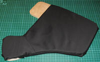
J'ai ensuite recouvert la mousse de tissus noir que j'avais acheté il y a longtemps pour fabriquer un sac pour des dés de Super Mario Dice. Les cotés rectilignes étaient faciles à gérer, mais le coté concave a demandé un peu d'efforts de couture : tout comme on ne peut pas recouvrir parfaitement une orange (sphérique) d'un feuille de papier (plane), on ne peut pas non plus recouvrir le repose-bras de tissus non-extensible (et le tissus extensible, c'est galère à utiliser, donc je n'ose même pas y penser).

repose-bras-gauche-habille-dessous

Le dessous est nettement plus simple: le tissus est agrafé (merci à Aku qui m'a prêté l'outil idoine).

repose-bras-droit-habille-dessus

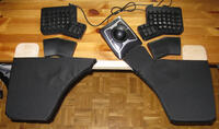
Le coté droit est plus compliqué à cause du repose-poignet qui ajoute un deuxième bord concave et une épaisseur supplémentaire. J'ai fini par comprendre (à force d'essayer de poser le tissus à plat sur toutes les parties où placer la deuxième couture. L'angle entre le repose-poignet et le bord supérieur par contre est très moche, j'ai dû y faire une découpe que j'ai recouverte d'un morceau de tissus collé à la colle chaude (c'est trop petit pour que j'arrive à y coudre une pièce). Enfin, le tissus est collé sous le repose-poignet, c'est très moche aussi mais personne n'ira regarder.

repose-bras-dessus-habille

Le résultat final.

Modification du 2022-08-18: j'ai collé deux morceaux de silicone (découpés dans un tapis de pâtisserie en silicone qui était abimé de coups de couteau) sous les parties du repose-bras qui prennent appui sur la surface du bureau, pour éviter qu'il ne glisse. Coller du silicone, c'est pas facile, la colle néoprène tient très bien sur le bois mais pas du tout sur le silicone. Le joint silicone en tube en revanche fait l'affaire (même si on pourrait le décoller en tirant fort dessus).

[ Postattu 11. elokuuta 2022 klo 09.54 | ei kommenttia | ]

Perjantai, 5. elokuuta 2022

Repose-bras (partie 1)

Käännös: [ Google ]

Kategoriat: [ Askartelu ]

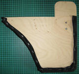
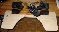
repose-bras-dessus

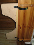
Pour rendre mon poste de travail plus confortable, je voulais y ajouter un repose-bras. Comme tous ceux que j'ai vus en ligne étaient trop étroits et mordaient sur le bord du bureau là où je veux mettre le trackball, j'ai décidé d'en construire un moi-même. How hard can it be? comme y disent (oui je sais le bord du repose-bras du commerce pourrait être utilisable pour remplacer celui du trackball, mais j'avais pas envie d'essayer pour me rendre compte que finalement, bah non, c'est pas top).

Celui que j'ai construit est composé de deux parties en contreplaqué de 12 mm (qui coûte justement un bras en ce moment, 36 ¤/m2, il doit être plaqué or à l'intérieur) fixées à un tasseau de 28 mm par six vis auto-taraudeuses 3x30 (à tête Torx, le Torx c'est bien, mangez-en. Je ne vois pas pourquoi on utiliserait encore du Pozidriv de nos jours ; d'ailleurs à Stark, on ne trouve plus que du Torx).

repose-bras-dessous

Le repose-bras est fixé au bord du bureau par un ingénieux système de crochets en acier, ce qui permet de l'enlever et le remettre rapidement. Je les ai trouvés sur ergostar.fi quand je regardais les modèles de repose-bras. Je ne suis pas sûr comment je l'aurais fixé si je n'avais pas trouvé ces crochets. Ces derniers sont ensuite vissés sur les bords du repose-bras (sous les parties que mordent justement sur le bureau) grâce à des écrous à frapper M5 (dont j'ai découvert l'existence en me promenant sur motonet.fi pour justement regarder comment je pourrais fixer le bazar en question) qui s'adaptent pile-poil aux vis M5 fournies avec les crochets.

Prochaine étape : trouver de la mousse pas trop épaisse pour rembourrer le dessus et la couvrir avec du tissus.

[ Postattu 5. elokuuta 2022 klo 15.14 | 1 kommentti | ]

Sunnuntai, 14. marraskuuta 2021

New Leffakone Infrared Receiver

Käännös: [ Google ]

Kategoriat: [ Askartelu/Arduino | TV/Leffakone ]

Several months ago, the leffakone infrared receiver started to misbehave. There were a lot of errors in syslog about spikes in the signal, and the problem seemed to come from the serial port on the motherboard rather than from the homebrew IR receiver, connected to the serial port, that I had built in 2002 or 2003 and that I had been using with lirc ever since. One of the symptoms was that unloading the lirc-serial kernel module caused the computer to freeze, while testing the receiver with an oscilloscope seemed to show that it was working correctly. For many months, I was too lazy to do something about it, as using a keyboard with a long enough cord was enough to control leffakone. During the last autumn vacation, I tried to test the receiver with the serial port on minikone, but the latter seems to deliver only 1.2V signals, when the receiver expects at least 7V to power its onboard voltage regulator. So that was not very conclusive.

leffakone_ir_receiver

At the same time, I had the idea of building a CO2 monitor using a Jeenode I had lying around, and somehow I wondered if the IR receiver module would not just fit into one of the Jeenode's ports. Guess what? It fits perfectly, allowing to use the IRQ pin as the input, which is exactly what the Arduino-IRremote library suggests to use. Writing the software was a bit of a headache, because the library assumes that the compiler would run with the -flto option (and the compilation ends with an error if it is not set), but my custom Makefile somehow fails to compile the code correctly if I enable that option. Thankfully, you can get around the problem with #define SUPPRESS_ERROR_MESSAGE_FOR_BEGIN. After that, the program is quite straightforward: configure it for the RC5 protocol (as this is what my remote control produces), read a code and write it to the serial port if it matches the RC5 address. I also added a new feature: if the code is the power on button, it would set a pin to HIGH for a short while, allowing to switch the computer on. I used the Jeenode USB as it has an on-board USB-to-serial adatpter, which makes it perfect to connect to a modern computer. I had one reed relay left from the timer and despite being rated for a 5V control voltage, it works with the Jeenode's 3.3V signal. The Jeenode is connected to the computer with a USB cable where I have replaced the USB Type A connector with a Molex connector so that I can use one of USB headers on the motherboard. Crimping the very small contacts was difficult as I don't have a crimping tool, but the connections seem to be working despite having done quite a poor job of it.

Yesterday, I installed the extra reed relay and the Jeenode onto the PCB that holds the relays of the timer, and now it's inside leffakone and working well. And since I forgot to take a picture, there is no image of what it looks like. In addition, I'm quite happy I have been able to do this project by using only bits and pieces I already had (the Jeenode, the headers, the reed relay, the IR receiver module, the USB cable, the Molex contacts and housing).

[ Postattu 14. marraskuuta 2021 klo 11.56 | ei kommenttia | ]

Tiistai, 2. marraskuuta 2021

CO2 Meter

Käännös: [ Google ]

Kategoriat: [ Askartelu/Arduino ]

CO2_Meter_ext

The last issue of Make: magazine had an article about building a CO2 monitor. The concentration of CO2 is apparently a good estimator for the concentration of SARS-CoV-2 in the air, which is correlated to the risk of transmission. The article suggests keeping the concentration of CO2 under 800 ppm when people are wearing masks.

The Make: article proposes a green-yellow-red light indicator, where the light is green when the concentration is below 1000 ppm, yellow above that level and red when it goes above 2000 ppm. These values are rather about indoors air quality and not directly related to limiting the transmission of SARS-CoV-2.

An article from NIST however indicates that the 1000 ppm limit has no basis whatsoever so I decided to use the 800 ppm limit instead and a rather arbitrary limit of 1300 ppm based on looking at Figure 2 in this article which seems to indicate that some cognitive abilities drop around that concentration.

Description

CO2_Meter_int

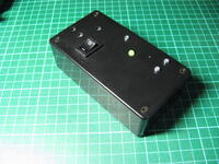
The device itself is quite simple: it has an on/off switch and a single two-color LED indicator, red and green. The yellow color is obtained by turning on both green and red colors at the same time. It also has a small hole where a paperclip can be inserted for triggering the calibration procedure. The holes next to the power switch expose the CO2 sensor and its temperature/humidity sensor.

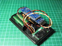
Inside the box there is an Arduino-like Jeenode I had lying around with an AA Power board (I have no idea if these are still sold, I've had them around for over ten years). The AA Power board is meant for a single AA battery, but it cannot provide enough current, so I removed the battery clips and connected it to a 2-AA battery holder, via the switch. It seems to be working well with two NiMH rechargeable batteries.

The CO2 sensor is a Sensirion SCD30. It is quite expensive (about 50 EUR), but has an easy to use I2C interface and is the most accurate of the sensors presented in the Make: article. The software is quite trivial (if you except the calibration procedure, see below), and available here. The device automatically makes a measurement ever two seconds, the program reads it and updates the LED accordingly. That's it.

Calibration

There is an automatic calibration procedure that requires to keep the sensor powered for at least 7 days and put it in fresh (outdoors) air at least an hour per day. This is not very practical given that I've estimated that the batteries would last about 25 hours (20 mA for the ATmega, 17 mA for the SCD30, 10 mA for the LED at 3.3 V, with maybe a 80% efficiency for the power board with two 1900 mAh batteries at 2.4 V). There is however also the possibility to expose the sensor to air with a known CO2 concentration and tell it the actual value it is measuring. It then uses this value as a reference point for subsequent measurements. The device is apparently sensitive to changes in shape (e.g. when subjected to mechanical stress during transport) so as a portable device it probably needs to be regularly re-calibrated.

The calibration procedure is simple: place the device outdoors, wait about 2 minutes for it to settle, then introduce a paperclip into the hole and press the button underneath it; the LED will be flashing red. The device will take repeated measurements every 2 seconds, and when a succession of 10 measurements is considered stable enough (i.e. the absolute value of the difference between the first and last of those is at most 1, and the sum of the absolute values of each measurement with its previous one is at most 10), it sets the calibration value to 416 ppm (which seems to be about the average value in 2021). As the device is accurate to +/- 30 ppm, the exact value does not matter so much. The device then returns to its normal operation mode, showing a green, yellow or red light.

What next?

Put a sticker on it with some indications about the LED colors and the reset button hole.

[ Postattu 2. marraskuuta 2021 klo 23.22 | 2 kommenttia | ]

Torstai, 21. marraskuuta 2019

Bed Reading Lamp

Käännös: [ Google ]

Kategoriat: [ Askartelu ]

For quite a while I have been dreaming about a lamp for reading in bed that would be equally usable when lying on my belly or sitting with my back on the wall. It would be wide enough to uniformly light an open comic book (slightly larger than an A3 paper sheet) without causing a glare on the paper, meaning that it should light from above. Finally it must be made of a strip of warm white LED, its brightness must be adjustable and must consume no power when it's off.

And because making things is fun, I wanted to make it myself. There it is.

Reading_lamp

It's made of 60 cm of LED strip glued on the inside of a 15×15 mm aluminium profile, and it's powered by a 12 V, 500 mA power supply, via a dimmer (that has also silly features like strobe effect, blinking and pulsating, but that's no good for reading). The power supply is connected to the mains via a wire equipped with a switch (that effectively cuts the power to the power supply when it's off).

Reading_lamp_wiring Reading_lamp_wiring_inside

To meet the requirement of reading in two different positions, the angle of the aluminium profile can be changed by rocking it. I had to solder thinner wires to the LED strip to prevent it from acting like a spring and holding the lamp back when rocking it.

Reading_lamp_position_A Reading_lamp_position_B

[ Postattu 21. marraskuuta 2019 klo 17.42 | ei kommenttia | ]

Keskiviikko, 23. joulukuuta 2015

Photo haute vitesse

Käännös: [ Google ]

Kategoriat: [ Askartelu/Arduino ]

hsphoto-ensemble

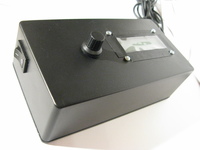
Cet appareil n'a pas de nom, mais il sert à controller un appareil photo et un flash pour prendre des photos d'objets qui tombent. Un rayon laser (récupéré d'un pointeur laser rouge bas de gamme) dont la présence est détectée par un phototrasistor sensible à la lumière visible est interrompu par l'objet qui tombe, et après un temps déterminé, le flash est déclenché.

Le code est disponible.

hsphoto-interface

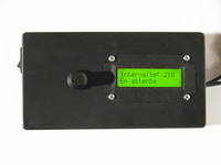
L'appareil utilise un RBBB (compatible Arduino, mais dans un format plus compact) pour contrôler un écran LCD alphanumérique, l'appareil photo via sa télécommande par câble, et le flash via son sabot. Il permet aussi de règler le délai entre la détection de la chute de l'objet et la prise de la photo. On peut en outre règler la longueur de l'impulsion du flash (ce qui n'est pas très utile apparemment, étant donné que cette durée n'a pas l'air d'avoir d'influence sur la durée du flash, mais cette durée détermine aussi le délai entre le déclenchement du flash et la fermeture de l'obturateur de l'appareil photo). En outre, on peut choisir à quel moment l'obturateur sera ouvert (avant de faire tomber l'objet à photographier, au moment où celui-ci coupe le faisceau laser, ou le mode manuel où l'utilisateur a la responsabilité d'ouvrir l'obturateur), et l'envoi ou non d'une impulsion pour effectuer la mise au point (la télécommande filaire est conçue de sorte à ce que le signal de mise au point soit toujours envoyé avant le signal d'ouverture de l'obturateur, il se peut que l'appareil ne fonctionne pas correctement si le second n'est pas précédé du premier).

hsphoto-pcb

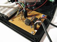
Le RBBB est alimenté par 4 batteries rechargeables NiMH, qui fournissent ensemble une tension maximale de 5,4 V, juste en dessous de la limite maximum du microcontrolleur (5,5 V). Ceci permet de se passer d'un régulteur de tension, à condition de ne pas utiliser de piles alcalines (qui produiraient une tension trop élevée, 6,6 V au maximum).

Une des difficultés a été que le laser tend à chauffer, ce qui diminue environ de moitié sa luminosité au bout de 30 s. À ce moment, le laser n'est alors plus assez puissant pour être détecté par le phototransitor. La seule solution est de ne pas laisser au laser le temps de chauffer.

hsphoto-cadre

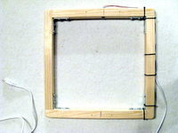
Une autre difficulté a été la construction du cadre en bois qui porte le laser et le phototransistor : il n'est pas parfaitement plan (je voulais le rendre démontable et j'ai donc utilisé des angles en acier à visser, mais comme je n'ai pas réussi à visser les vis bien verticalement, elles ont déplacé légèrement les angles et tordu les quatre morceaux de bois). De plus, il n'est pas facile de percer un trou bien droit (pour recevoir le laser) et aligné avec un trou similaire (pour recevoir le phototransitor) sur le coté opposé du cadre.

hsphoto-laser

Pour aligner le laser sur le phototransistor, il faut donc tourner un peu le premier dans son logement jusqu'à ce que le point rouge atteigne le centre du phototransistor. L'appareil dispose d'ailleurs d'un mode de fonctionnement où le laser est allumé en permanence et où l'utilisateur peut voir si le phototransistor est correctement éclairé.

La dernière difficulté a été de me rendre compte que le temps de chute de l'objet (entre le moment où le laser est interrompu et le moment où la photo doit être prise) dépend de la vitesse de l'objet au moment où il passe dans le faisceau laser, donc de la hauteur (au dessus du faisceau) d'où l'objet a été laché. Pour obtenir des expériences répétables, il faut donc faire tomber l'objet à partir du support sur lequel il repose, et il faut donc que ce support soit à une distance connue du faisceau. Le support est donc un morceau de carton ondulé percé d'un trou assez grand pour laisser passer l'objet (mais pas trop grand pour que l'objet ne puisse pas tomber à coté du faiscea) posé sur le cadre en bois. La distance d entre le haut du carton et le faisceau, la hauteur de chute h du haut du carton jusq'à l'endroit où la photo est prise et le temps de chute t sont liés par l'équation suivante : t = √(2/g) × (√h - √d) où g est l'accélération de la pesanteur.

hsphoto_de_1 hsphoto_azrael hsphoto_bonhomme

[ Postattu 23. joulukuuta 2015 klo 23.45 | ei kommenttia | ]

Sunnuntai, 4. toukokuuta 2014

New Leffakone Timer

Käännös: [ Google ]

Kategoriat: [ Askartelu/Arduino | TV/Leffakone ]

new_leffakone_timer

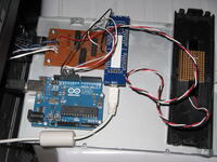
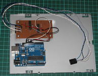
I finally built the timer for the new Leffakone. It is based on an Arduino Uno, which controls two reed relays and one LED. The reed relays can be activated with a very low current (10 mA), meaning that the Arduino can drive them directly from any I/O pin. The relays' contacts are connected in parallel to the power button and the reset button. The Arduino's serial-over-USB port is connected to one of the USB headers of the motherboard with a home-made cable, and the timer is set by software through this serial connection. All the wires coming from the computer case's front panel are connected to the circuit (to the 8-pin header protruding from the protoboard), and wires go from there to the motherboard's front-panel header (2 white wires for the power button, 2 grey wires for the reset button, and 2 blue+black wires for the power-on LED. The two boards are screwed on the bottom plate of the case of an old CD drive; for installation, I closed the case and put it into the computer as a regular CD drive.

While the timer is counting down, it blinks the computer case's HDD LED (which therefore is not anymore indicating the HDD activity).

When the timer expires, it closes the power button's relay for 500 ms. An optional watchdog timer would close the reset button's relay if the machine does not boot correctly i.e., if the timer is not reset within 30 s. This watchdog timer is currently disabled in the code, since the problems I have had with GRUB freezing on startup seem to be related to manually powering the device and switching the TV on shortly after. I'll enable it if it seems necessary. Here is the code for the Arduino.

The software client for the timer is written in Python and is very straightforward: send ASCII digits to the serial port, ending with a newline character. It interprets this number as a number of seconds, and starts counting down. When disconnecting the client from the serial port, the Arduino resets and forgets all about the timer value; I found out that setting the DTR line to False in the Python Serial object prevents this from happeining. I haven't however found out how to prevent a reset when connecting to the Arduino; this is less a problem, since when I connect to it, I want to reset the timer, and reseting the whole program does just that. It seems that it's the Linux driver that asserts the DTR line when opening the serial port; I haven't investigated further. It is worth noting that when the machine boots, it does not reset the Arduino.

Finally, the cristal in the Arduino is accurate to 99.5% which is not enough to guarantee that the timer will wake up the computer within a minute after a countdown of several days. I therefore apply a corrective factor to the time sent to the Arduino. The factor was estimated from a 15.5 hour countdown, which lasted about 90s more than it should have. Over a 7-days countdown, it would cause the timer to expire about 16 minutes too late.

[ Postattu 4. toukokuuta 2014 klo 20.38 | 1 kommentti | ]

Tiistai, 19. helmikuuta 2013

Machine Inutile

Käännös: [ Google ]

Kategoriat: [ Askartelu ]

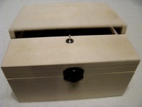
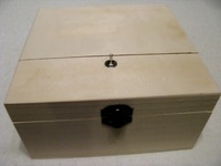
Quand on bascule l'interrupteur, un doigt sort de la boite et le rebascule dans l'autre sens. Strictement inutile, et donc parfaitement indispensable.

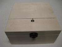
machine_inutile_1

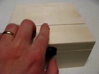
Vue de l'extérieur, c'est une boite en bois blanc, sans fioriture, à part l'interrupteur sur le couvercle.

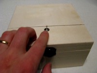
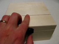
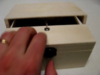
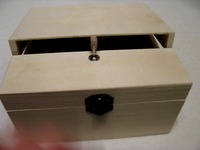
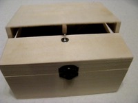
Quand on pousse l'interrupteur, voici ce qui se passe:

machine_inutile_ralenti_1 machine_inutile_ralenti_2 machine_inutile_ralenti_3 machine_inutile_ralenti_4 machine_inutile_ralenti_5 machine_inutile_ralenti_6 machine_inutile_ralenti_7 machine_inutile_ralenti_8

La vidéo de la boite en action est également disponible.

machine_inutile_2

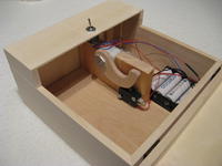
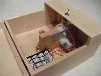
Sous le capot, un moteur équipé d'une boite de vitesse 1:228, alimenté par 4 batteries rechargeables. Lorsqu'on bascule l'interrupteur, le « doigt » se lève, bascule l'interrupteur dans l'autre sens, ce qui renverse la la polarité et fait tourner le moteur dans le sens inverse. Le « doigt » revient alors à sa position initiale et finit sa course sur un deuxième interrupteur, qui coupe le courant. Le moteur s'arrête.

machine_inutile_3

Mécaniquement et électriquement, il n'y a rien de compliqué, à part le fait de positionner les pièces au bon endroit.

Pour finir, une vidéo de la machine en action couvercle levé. On remarque que le « doigt » sursaute en arrivant sur l'interrupteur, au moment où le courant se coupe, et revient s'y poser une deuxième fois plus doucement, et reste en place.

[ Postattu 19. helmikuuta 2013 klo 21.51 | ei kommenttia | ]

Torstai, 22. maaliskuuta 2012

Car Heater Controller

Käännös: [ Google ]

Kategoriat: [ Askartelu/Arduino ]

heater_controller_2

Finnish winters are cold, and petrol engines don't like starting when it's very cold. That's why cars are often equipped with an electric heater that preheat's the cooling liquid for some time before starting the engine. The duration of this pre-heating depends on the temperature (in French). Moreover, since I don't leave home every morning at the same time, I don't want to start heating the car at the same time every day, even if the outside temperature doesn't change much from day to day. Hence this project of a remote-controlled switch for the car heater.

The system is composed of two Arduino-compatible parts: one master, connected to the home computer (always on), and one slave, in the garage. The master is a JeeLink and the slave is based on a JeeNode. Master and slave communicate with each other with a radio (868 MHz, a free Low-power_communication_device band in Europe).

The master

Not much to say about the master, the hardware is a standard JeeLink, which for the purpose of this project is really only a radio transceiver on a Serial-over-USB interface.

The slave
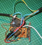
heater_controller_1

The electronic is very simple, and only a few components are needed. I paid special attention to selecting components that are specified to work from -40 °C (although I have no idea how well the device works at that temperature).

The slave is organised around a JeeNode (vertical, in the right-hand corner of the picture), and has the following three features.

It controls a relay (the black box above the orange PCB on the picture), which can be open or closed.

It measures the outside temperature with a DS18S20 sensor.

It measures the current flowing out of the relay using a current transformer (the black ring aroung the brown wire on the left side of the picture).

Moreover, it has a power supply (the black box on the lower left corner of the picture).

You can also notice that the mains cable (a 5 m, outdoors prolongation cord) has an earth wire that has not been severed. The live (brown) and neutral (blue) wires have been cut and connected to the relay. Power for the power supply is taken from the plug-side of the cable, before the relay (so it's always connected to the mains).

Power supply

The power comes from a compact switching power supply that converts 230 V AC into 12 V DC (maximum output power: 4 W). In case the power supply fails, the 1 A fuse (in the holder on the big red wire on the lower-left corner of the picture) should blow before the whole thing catches on fire. Also, although the power supply is designed to be placed on a PCB, I decided not to have any 230 VAC on the PCB, so I soldered the wires straight to its input pins, and isolated them with heat-shrink tube and added epoxy for strenght (the pins are not so strong, I don't want to break them once they are connected to the thick and not-so-flexible wires).

The relay requires 12 V, hence the output value for the power supply. The JeeNode requires a 3.3 V supply, and the onboard voltage regulator could take the 12 V, but would ouput only a low current (less than 100 mA). By adding a 5 V regulator (7805) to supply the JeeNode, the latter can get more current from its on-board regulator.

Relay

The relay (specified to switch up to 400 VAC and 30 A) requires 160 mA to be activated. It is therefore controlled via a BC337 transistor, which is strong enough to withstand the current. The base of the transistor is connected to one digital pin of the JeeNode via a 2 kΩ resistor, which allows to open or close the relay by applying a High or Low signal to that pin.

Temperature sensor
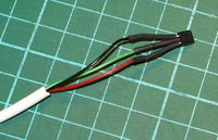
heater_controller_temperature_sensor

The DS18S20 transmits the temperture information digitally over a 1-Wire bus, and therefore requires really nothing more than a 4.7 kΩ pull-up resistor. It works quite happily with 3.3 V at the end of a 15 m cable (an old phone extension cord). Note that since I have three wires in the cable, I didn't even try to power the sensor with parasitic power (anyway, I read somewhere that it doesn't work well at 3.3 V). The Arduino OneWire library does all the work for you, all you need is to connect the data pin of the sensor to one digital input of the JeeNode.

Current sensor

Finally, the current transformer is placed around the live wire coming out of the relay. The design is based on a page at OpenEnergyMonitor that does not appear to exist anymore, but this one should give a good start.

Basically, the current transformer produces a current (not a voltage) that is proportional (depending on the number of turns, my transformer has 1012 turns) to the current flowing through the mains wire that goes through the transformer. A burden resistor (68 Ω in my case) across the two wires produces an AC voltage that is proportional to this current and varies between -1.65 and +1.65 V (corresponding to mains current between -23 and +23 A peak-to-peak). Then one wire of the transformer is connected to a voltage divider made of two 20 kΩ resistors (with a filtering 47 μF capacitor) and the other wire goes to one of the analog inputs of the JeeNode. This way, the analog input sees a voltage that varies between 0 and 3.3 V, which is within the tolerance of the device.

After that, the software samples the analog value 3000 times, applies a high-pass filter to remove the DC offset, and simple math computes the RMS current. After a bit of calibration (using a 60 W lamp, and 500 W halogen lamp, a 1400 W flat iron and a 2300 W electric kettle, and comparing my measurments against those of a wattmeter), I noticed that the reported current is quite accurate (to about 0.01 A, which is more than enough for my purposes).

Box
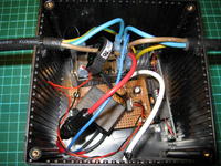
heater_controller_in_box

The PCB and the relay a screwed on a piece of plexiglas, and the whole device is placed in a project box to protect it from dust. Zip ties around the cables near the holes prevent the cables from being accidentally pulled out of the box.

Schematics
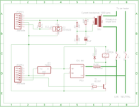
heater_controller

The schematics are available as a PNG picture, and in Eagle format. Note that since I used strip board to assemble the circuit, I haven't paid attention to choosing the right component packages, nor the right type of component. The Eagle schematics is therefore provided for information purposes only, generating a board from it is not going to produce correct results.

The Software

It's all available there. You can obtain it with git using the command
git clone http://weber.fi.eu.org/software/arduino/heater_controller/.git/
[ Postattu 22. maaliskuuta 2012 klo 23.23 | 1 kommentti | ]

Torstai, 9. helmikuuta 2012

Stripboard Sketch Paper

Käännös: [ Google ]

Kategoriat: [ Askartelu ]

proto_board_sketch

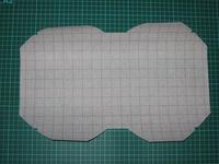
I don't like to start soldering on a stripboard without having sketched the positions of the different components beforehand on a paper. While this is easily done on the back of an envelope, having 1:1 scale sketchpaper would be handy. So I made such a printable sketchpaper.

[ Postattu 9. helmikuuta 2012 klo 08.55 | ei kommenttia | ]

Keskiviikko, 28. joulukuuta 2011

Timelapse Controler

Käännös: [ Google ]

Kategoriat: [ Askartelu/Arduino ]

timelapse_controller

The timelapse photography controller I helped a friend build is finally complete. He built the hardware, I wrote the software. The latter is uselessly complicated, but I wanted to have fun with C++ and multiple inheritance, so here it is. The device is controlled by a rotary encoder with an integrated push button and a 2x16 character LCD display. It also has a plug to connect it to the camera (via a 2-channel optocoupler) and is powered with 4 AA batteries.

The UI is composed of 4 screens:

  • a status screen, showing how many pictures have been taken so far, as well as the voltage of the batteries
  • a start/stop screen
  • a screen for setting the number of pictures
  • a screen for setting the time interval between the pictures.

Turning the knob moves from one screen to the other, while pressing its button activates the current screen (e.g., starting or stopping, or allowing to change the value of e.g., the time interval).

The last two screens are disabled when the timer is started, and re-enabled when it is stopped. Also, the screen is turned off after a 10s timeout, and switched back on when the button is pressed or the knob is rotated. This allows to reduce the power consumption from abuot 24 mA to 8 mA. This way, a set of 2000 mAh rechargeable batteries should last over 200 hours.

[ Postattu 28. joulukuuta 2011 klo 20.40 | ei kommenttia | ]

Perjantai, 2. joulukuuta 2011

Don't Forget pinMode()

Käännös: [ Google ]

Kategoriat: [ Askartelu/Arduino ]

I spent hours with a friend trying to solve the following problem: an LED and a 430R resistor are connected to the pin of an Arduino (actually an RBBB powered with 3.3 V). Using digitalWrite(pin, HIGH) it did light the LED, but it was very dim. What was more weird, is that the pin was showing only 1 V instead of 3.3 V. After two hours of scratching our heads, I looked up on Google and found the answer: “don't forget to call pinMode(pin, OUTPUT)…”

At boot time, the pins are set as inputs. digitalWrite(pin, HIGH) switches the internal pullup resistor (20K – 50K), which is enough to allows the pin to source a little bit of current at a quite low voltage. It was enough the dimly light the LED, but not enough to get the optocoupler (that was initially connected to the pin) to work properly.

[ Postattu 2. joulukuuta 2011 klo 16.38 | ei kommenttia | ]

Maanantai, 15. elokuuta 2011

Hardware Random Number Generator

Käännös: [ Google ]

Kategoriat: [ Askartelu/Arduino | ATK ]

whitenoise

Software random number generators are usually so-called pseudo-random number generators, because they produce a deterministic sequence of numbers that have some of the properties of true random numbers. Obtaining genuinly random numbers howerver requires a non-deterministic processus as the source of randomness. Thermal noise in electronics or radioactive decay have been used, usually requiring an external device to be built and plugged to the computer.

Peter Knight's TrueRandom generates random bits by using the Arduino's ADC (with nothing connected to the analog input pin) to measure electronic noise. It flips the pin's internal pull-up resistor while the measure takes place to increase the amount of noise. The software then keeps only the least significant bit of the result, filters it using Von Neumann's whitening algorithm (read pairs of bits until they are of different values and return 0 (respectively 1) on a 01 (respectively 10) transition). There are several functions that generate different types of numbers based on those random bits.

I reused that code, modified it to allow using another pin than the Arduino's Analog0 and I made my own random number generator. I also wrote a Python script that reads the bits from the serial port, uses the SHA-1 hashing algorithm to distil the data (the raw data has about 6 bit of entropy per byte, distillation produces data with 7.999 bits of entropy per byte; based on the work of Jeff Connelly on IMOTP) and writes them to the standard output or into a file. On my Duemilanove, it can output about 1500 bits/s, while it outputs 1300 bits/s on a JeeLink. The latter makes it an easy-to-transport device that is reasonnably sturdy and fits in the pocket, even if its features (it contains a radio transceiver) are a bit overkill for the job (not to mention expensive).

I also adapted the core of the TrueRandom software to run on my ButtonBox (which is conveniently always connected to my desktop computer). There the output rate is a mere 300 bps, but it's still reasonnably fast for generating a few random numbers when needed (for example for generating one's own PasswordCard). The access to the ButtonBox is shared among multiple clients using button_box_server.py, so a modified Python script was used for obtaining the stream of random bits through the button_box_server.

I haven't had the patience to generate a few megabytes of random data to test the generator with the DieHarder test suite, but the output of Fourmilab's ent test tool looks reasonnable.

[ Postattu 15. elokuuta 2011 klo 11.08 | 2 kommenttia | ]

Torstai, 16. kesäkuuta 2011

The Infernal Op Amp

Käännös: [ Google ]

Kategoriat: [ Askartelu ]

differential_amplifier

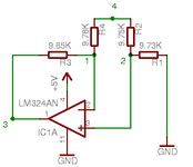
This is driving me crazy. To the left (click the image for a bigger version), you can see a basic differential amplifier based on a LM324AN op amp. If the op amp is perfect and the resistors are be exactly 10 kΩ, the potential Vout (on point 3) would be equal to the difference of potential between V+ and V- (on points 2 and 1, respectively). In other words, Vout = V+ - V-.

When working with a real op amp, the things are not that simple, but they should remain quite close to the ideal case. In fact, if we set V4 to GND, we get reasonnable values. However, if we se V4 to +5.05V (which is also the positive supply of the op amp), the values don't make sense to me anymore.

Here's what I measured (the millivolt values are at least ±0.1 mV, but the volt values should be reasonnably accurate):

V4 set to0 V+5.05 V
V- =1.3 mV2.83 V
V+ =0.1 mV2.51 V
Vout =1.9 mV0.65 V

When V4 is set to 0 V, the values of V- and V+ seem to be consistent with the specs of the chip regarding input offset current and input bias current (input current of 100 nA accross a 10 kΩ resistor is 1 mV).

When V4 is set to 5.05 V however, I really don't understand what laws of physics makes the difference between V+ and V- so large (0.32 V, which just happens to be half of Vout. But that's maybe just a coincidence). Further experiments have shown that Vout remains constant at 0.65 V when 2.7 V < V4 < 5.05 V, but decreases when V4 < 2.7 V.

The goal of the device is to measure the voltage across a 0.05 Ω shunt which would be placed at point 4, with 5 V applied on its R4 side and the load (a low-power electric motor) between the shunt's R2 side and the ground.

Any comment on the subject will be appreciated.

[ Postattu 16. kesäkuuta 2011 klo 09.42 | 1 kommentti | ]

Current Monitor

Käännös: [ Google ]

Kategoriat: [ Askartelu ]

current_monitor

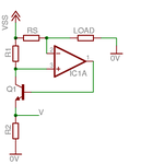
This schematics of a current monitor can be found in many datasheets as examples of applications of an op amp. I wanted to find out the relationships between RS (the shunt), R1 and R2. Here's how it goes:

  • V1 = A·(V+ - V-) (1) (A is the open-loop gain of the op amp)
  • V+ = VSS - V·R1/R2 (2) (Common emitter transistor setup, see more particularly this image)
  • V- = VSS - RS·iload (3)
  • V = V1 - 0.65 (4) (voltage drop between the base and the emitter of a common transistor)

Combining (2), (3) and (4) into (1), we get

V + 0.65 = A·(VSS - V·R1/R2 - VSS + RS·iload),

from which follows

V·(1 + A·R1/R2) + 0.65 = A·RS·iload.

We assume A is very large, therefore A·R1/R2 >> 1, so it simplifies into

V·R1/R2 + 0.65/A = RS·iload.

We assume A is very large, and thus 0.65/A << V·R1/R2, leading to

iload = V·R1/(R2·RS).

[ Postattu 16. kesäkuuta 2011 klo 09.40 | 1 kommentti | ]

Tiistai, 24. toukokuuta 2011

New Op Amp

Käännös: [ Google ]

Kategoriat: [ Askartelu ]

I finally got the courage to try out the new op amp model (LT1495) I received last week.

I tried out the current monitor circuit, and it works. The supply voltage for the op amp was 5 V, and I measured the current going through a red LED, powered with 15 V (coming from a supposedly 12 V power adapter). The measurement was 33,6 mA instead of the 31 mA given by the amperemeter. Not very accurate, but I don't actually need high accuracy.

Next step: trying to re-build the motor speed-controller circuit, get it stable enough that it doesn't reboot the Arduino all the time, and check how the current monitor behaves when the current is switching on and off all the time.

[ Postattu 24. toukokuuta 2011 klo 21.52 | ei kommenttia | ]

Maanantai, 16. toukokuuta 2011

Tyco Slot-Car Controller A/D Conversion

Käännös: [ Google ]

Kategoriat: [ Askartelu/Arduino ]

tyco_controller_adc

I hooked the Tyco slot-car controller to the Arduino's analog input with a 400 Ω pullup, and set the A/D converter's reference voltage to INTERNAL (meaning 1.1 V). The sampling rate is 100 Hz and the output values are between 0 and 1023. The movements are two successive slow squeezing-and-releasing of the trigger, followed by three quick squeeze-and-release.

  • In the lower picture (red) are the raw data.
  • In the second lower picture (green), the raw data is filtered by a 4th-order, low-pass Butterworth filter, with a 5 Hz cutoff frequency.
  • In the third lower picture (blue), a 32-levels quantization is applied to the raw data.
  • In the top picture (purple), the quantization is applied to the filtered data.

A value of 1023 (the maximum) indicates that the electrical contact is broken i.e., that the trigger is in the rest position or its maximum.

I have tried hardware filtering with capacitors (1 nF, 100 nF and 1μF), but the digital filter gives the best results. I don't doubt that more advanced hardware filters would have produced similar, if not better results, but they would have required more components, and if you can afford to do it in software, why bother with the extra hardware? Software filtering is amazing… The code for the software filter has been generated on this very useful website.

Additionally, conductive grease applied to the variable resistor may reduce quite much the noise (or shortcut the whole coil of wire…)

[ Postattu 16. toukokuuta 2011 klo 21.56 | ei kommenttia | ]

Sunnuntai, 15. toukokuuta 2011

The Infernal Op Amp 2

Käännös: [ Google ]

Kategoriat: [ Askartelu ]

I don't have a proper explanation as for the why, but the op amp problem I had recently is solved by using a virtual ground set to 1/2 Vsupply.

My understanding there is that the differential amplifier acts as both an inverting and non inverting amplifier, and that it needs a negative supply (or a virtual ground, which amounts to the same thing) for the non-inverting part. Using a virtual ground as mentioned above has two drawbacks:

  • it brings the reference point of Vout to 1/2 Vsupply, which makes it much less nice to use with the Arduino's analog input (only the upper-half of the input range is used because of this offset) and
  • the maximum allowable range for the signals is between 1/2 Vsupply and Vsupply-1.5V (for the LM324), which is not much even when Vsupply is 12 V.

Moreover, the differential amplifier needs well matched resistors: R1||R2 = R3||R4 (R1||R2 is the equivalent resistance of R1 in parallel with R2), othwerwise it has an additional DC offset which gets amplified by the gain of the differential amplifier, making the whole thing useless for my purpose of amplifying the very small voltage across a shunt.

On the bright side though, I found another op amp, the LT1495, that can accept inputs beyond Vsupply and with a very low input offset. Its only drawback is that it costs 25 times more than the LM324 (which was very, very cheap, but still).

[ Postattu 15. toukokuuta 2011 klo 20.52 | 1 kommentti | ]

Lauantai, 7. toukokuuta 2011

Slot Car Speed Controller

Käännös: [ Google ]

Kategoriat: [ Askartelu/Arduino ]

I just tested the first prototype of the speed controller for the Tyco slot cars. Currently, the Arduino reads the potentiometer with analogRead() and applies PWM (with analogWrite()) on the base of a BC547 transistor. The transistor acts as a driver for a FQP70N10 MOSFET which controls the motor. The MOSFET doesn't seem to heat at all (I selected this model for exactly that reason) and speed control works (i.e., I can drive the car on a simple ring circuit, down to quite low speed).

My initial idea was to drive the MOSFET directly with the Arduino, but I noticed after buying a pair of those that they it's not a logic-level MOSFET. Driving it with 5 V would theoretically work (I need about 1 A, which is well within the capabilities of the device), but the internal resistance would be much higher that the value touted on the datasheet, and thus dissipate more heat (exact figures for the resistance at 5 V are not available from the datasheet).

This was a proof of concept, and the concept is therefore proven, I can start working on measuring, with the Arduino, the current delivered to the motor.

[ Postattu 7. toukokuuta 2011 klo 22.21 | ei kommenttia | ]

Maanantai, 14. maaliskuuta 2011

Arduino Workbench

Käännös: [ Google ]

Kategoriat: [ Askartelu/Arduino ]

Arduino_workbench

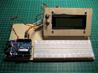
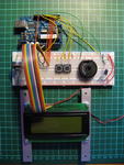
Here's a mini-workbench for Arduino prototyping, made of 6.5 mm plywood.

The Arduino board stands on whatever-they-are-called threaded thinggies you use to screw the motherboard into the computer case without it touching the metal. Arduino screw holes are 3.2 mm in diameter, so I had to drill them to 3.5 mm. It survived the treatment.

The breadboard had an adhesive back, so this one was easy.

The LCD has one potentiometer (top) for contrast and one switch for the LED backlight (depending on the power source, backlight may consume too much current, so it can be switched off if needed). The connectors at the end of the ribbon cable are made from component legs and shrink tube.

The drawback is that now it takes much more space than it used too…

[ Postattu 14. maaliskuuta 2011 klo 22.29 | ei kommenttia | ]

Lauantai, 12. helmikuuta 2011

Button Box

Käännös: [ Google ]

Kategoriat: [ Askartelu ]

ButtonBox7

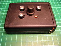
Here's the Button Box. It has three illuminated push-buttons, one knob (which also acts as a push-button) and one light-dependent resistor (the small thinggy on the lower-right corner) which are controlled by an RBBB microcontrller (software-compatible with the Arduino). Here's the control software.

ButtonBox9

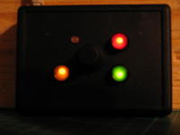
The push-buttons contain each one bi-color LED (red-green); its color depends on the direction of the current. Each LED which is controlled using PWM, which allows to quickly reverse the direction of the current and create the illusion of a yellow/orange color. Moreover, the Box senses the amount of ambient light (with the light-dependent resistor) and adjust the intensity of the light depending on that: by night, the LEDs are on only 1/64th of the time, while in daylight they are on at 100%, making them more visible.

ButtonBox8

It connects to the computer through a serial-to-USB adapter. It's a bit ugly like that, but who cares.

ButtonBox1

The current through the LEDs is limited by a 150 Ω resistor. The push-buttons use the microconstroller's internal pull-up resistors. The light-dependent resistor (rated 4 – 11 kΩ, whatever this exactly means) forms a voltage divider with a 1 kΩ resistor, and its value is read by one of the analog inputs of the microcontroller.

ButtonBox3

The white PCB is the RBBB, which is powered by the USB-BUB (serial-to-USB adapter, based on an FTDI chip). It's not the cheapest solution, but those components were the easiest to obtain.

ButtonBox4

The USB-BUB has its outputs rewired to the row of holes along its side, and is soldered sideways to the RBBB using a row of pin headers. The RBBB is then screwed through one ready-made hole to the bottom of the box through an additional piece of plastic glued (with cyanoacrylate glue) to the bottom. This gives a thickness of almost 5 mm which is enough to hold the screw (a bit thicker would have been better). The same is done to the other end of the RBBB which has a similar hole. This holds the USB-BUB enough for the USB cable to be inserted and removed.

ButtonBox5

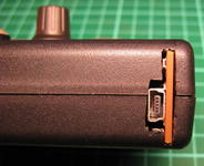
Side view. ABS project boxed are nice, because they are easy to drill and cut through with a hacksaw or even with a knife for smaller details.

ButtonBox6

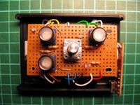
Inside view with the side walls removed. It's quite tight inside, but it fits nicely.

[ Postattu 12. helmikuuta 2011 klo 23.04 | 3 kommenttia | ]

Torstai, 30. joulukuuta 2010

Compte tours pour circuit auto, troisième partie

Käännös: [ Google ]

Kategoriat: [ Askartelu ]

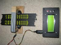
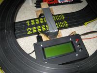
Portique_et_boitier

Le compte tours est enfin terminé, équipé d'une nouvelle version du logiciel afin de corriger des bugs (signal de faux départ lorsque la voiture démarre pendant la configuration, calcul erroné de la durée du premier tour) et d'ajouter des fonctionnalités (un appui sur l'un des deux boutons noirs pendant la course termine le chronométrage et revient à l'écran de configuration sans perdre la configuration précédente). Le bouton RESET (rouge) devient inutile, sauf en cas de plantage du logiciel, ce qui n'est pas encore arrivé.

portique_et_boitier_en_place

Voici le portique que j'avais construit l'été dernier. Il est en place dans le circuit de Noël 2010 et relié au boitier.

Portique_LEDs_IR

Les LEDs infrarouges sont montées sur le portique et éclairent la piste.

LEDs_IR

Elles sont montées en série avec une résistance 82 Ω et alimentées sous 5 V, ce qui donne un courant de 12 mA environ.

Portique_phototransistors

La lumière des LED infrarouges est détectée par des phototransistors placés sous la piste. Les rails de guidage du morceau de piste servant à l'origine de compte-tours sont percés de fentes (le picot de guidage des voitures faisait avancer à travers cette fente une roue portant des nombres), et la lumière d'une LED peut donc atteindre le phototransistor correspondant, qui reste cependant bien protégé de la lumière ambiante.

Phototransistors

Chaque phototransistor est relié au +5 V par une résistance pull-up de 1 kΩ. Les entrées de l'Arduino sont connectées aux collecteurs des phototransistors. Lorsque ces derniers sont éclairés, le signal est bas (0), et lorsqu'une voiture passe, il est haut (1).

[ Postattu 30. joulukuuta 2010 klo 13.58 | 1 kommentti | ]

Torstai, 16. joulukuuta 2010

Compte-tours pour circuit auto, deuxième partie

Käännös: [ Google ]

Kategoriat: [ Askartelu ]

Après plusieurs mois à prendre la poussière, j'ai finalement acheté les composants nécessaires pour construire une version fonctionnelle du compte tour pour circuit auto. Le circuit est le même que celui du prototype, mais l'Arduino Duemilanueve a été remplacé par un RBBB, plus petit et nettement moins cher.

Compte_Tours_boitier_dessus

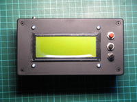
L'interface utilisateur se compose d'un écran LCD (4 lignes de 20 caractères) et trois bouton. Le bouton rouge est relié au reset de l'Arduino. Les bouton noir du milieu sert à choisir l'item suivant dans le menu, et le bouton du bas sert à agir sur l'item sélectionné.

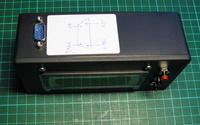
Compte_Tours_boitier_arriere

À l'arrière du boitier se trouve un connecteur D-sub à 9 plots récupéré sur une vieille carte mère, où le connecteur du port série était encore relié à la carte par un cable ruban. 4 plots sont utilisés : +5V, 0V, et les signaux venant des pistes 1 et 2.

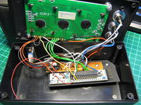
Compte_Tours_boitier_interieur

Le circuit blanc est le RBBB, le brun est morceau de carte à prototyper. Il comporte le potentiomètre pour le contraste de l'écran, et les différentes résistance (pull-down des boutons noirs, limiteur de courant du buzzer). La paire de fils rouge/noir devant à gauche vont au buzzer qui est fixé sur la face avant, derrière un petit trou. Les deux circuits sont fixés par des vis sur le morceau de boitier que j'ai découpé pour laisser passer l'écran, et ce moreceau est vissé sur le fond sur un plot prévu à cet effet.

L'écran LCD est connecté en mode 4bits, et comme le rétro-éclairage contient déjà deux résistance de 10 Ω en parallèle, j'ai pu le brancher directement sur le +5V.

[ Postattu 16. joulukuuta 2010 klo 13.21 | 1 kommentti | ]

Maanantai, 16. elokuuta 2010

Compte tours (prototype)

Käännös: [ Google ]

Kategoriat: [ Askartelu/Arduino ]

Compte_Tours_Proto

Le prototype de la partie électronique du compte-tours pour circuit auto est prêt. Le code source est disponible .

La diode IR et le phototransistor sur la droite permettent de simuler le passage de la voiture sur une piste. Le buzzer juste à coté donne le départ avec un signal sonore, signale un faux départ avec un autre signal sonore et la fin de la course avec un troisième. Les deux boutons au milieu permettent de choisir les options du menu.

Le menu propose trois options, une par ligne. Un des boutons permet de passer à la ligne suivante (et repart du haut une fois arrivé à la dernière ligne), l'autre permet d'activer l'option choisie. La première option permet de choisir le nombre de tours de la course ; la second permet alternativement de choisir la durée de la course (en minutes) ; la troisième démarre la course.

Durant la course, pour chacune des deux pistes, le nombre de tours parcourus est affiché, ainsi que le chronomètre du tour en cours, le chronomètre de la durée totale de la course et, après le premier tour, la durée du tour le plus court.

Lorsque le nombre de tours est atteint par un des participants, ses chronomètres sont arrêtés et le signal de fin de la course retentit. Lorsque l'autre participant parvient au nombre de tours choisi, ses chronomètres sont arrêtés à leur tour.

Lorsque la durée choisie est écoulée, les deux chronomètres sont arrêtés.

[ Postattu 16. elokuuta 2010 klo 21.02 | 1 kommentti | ]

Torstai, 12. elokuuta 2010

Oscilloscope rudimentaire

Käännös: [ Google ]

Kategoriat: [ Askartelu/Arduino ]

J'ai bricolé hier un script python/GTK qui représente de manière graphique les données produites par le programme-exemple AnalogInSerial. Le code source sans documentation se trouve . Le code est dans le domaine public.

arduino_oscilloscope_noise

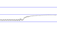
L'entrée analogique n'étant reliée à rien, elle produit surtout du bruit, de fréquence régulière (trop lent pour être les 50 Hz du secteur, mais comme la fréquence d'échantillonage est de l'ordre de 70 Hz, il se peut que le signal soit mal échantilloné) et d'amplitude constante.

arduino_oscilloscope_up

Ce qui est plus surprenant, c'est que l'amplitude du bruit diminue lorsque l'Arduino est soulevé de la table.

arduino_oscilloscope_tap

L'amplitude augmente temporairement lorsqu'on tapote le connecteur (ici le circuit est posé sur la table).

arduino_oscilloscope_blow

La valeur moyenne lue augmente lorsqu'on souffle sur le connecteur (le circuit est en l'air), tandis que l'amplitude des oscillations diminue. Ensuite, la valeur moyenne diminue très progressivement (sur plusieurs secondes), avant de retrouver son niveau de départ.

[ Postattu 12. elokuuta 2010 klo 22.46 | 4 kommenttia | ]

Keskiviikko, 11. elokuuta 2010

Hello World LCD

Käännös: [ Google ]

Kategoriat: [ Askartelu/Arduino ]

Arduino_LCD_1

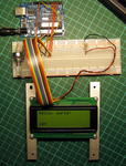
J'ai récupéré l'écran LCD (4 lignes de 20 caractères) de feu Poppikone et je l'ai branché sur l'Arduino. Le Hello World livré en exemple avec la bibiothèque LiquidCrystal fonctionne :)

[ Postattu 11. elokuuta 2010 klo 23.51 | ei kommenttia | ]

Tiistai, 27. heinäkuuta 2010

Compte-tours pour circuit auto, première partie

Käännös: [ Google ]

Kategoriat: [ Askartelu ]

But du projet: construire un compte-tours électronique pour mon vieux circuit auto Tyco. Le portique est prêt : deux diodes IR éclairent la piste juste au dessus des voitures. Le compteur mécanique original fonctionnait grâce à un morceau de piste spécial, dont le rail guide était ouvert sur le dessous pour permettre à l'ergot des voitures de faire tourner une roue numérotée. J'ai placé deux phototransistors sous ces fentes : en temps normal, ils reçoivent le faisceau des diodes IR, mais quand une voiture passe, celui-ci est interrompu.

L'interface de sortie est simple à souhait : un fil pour chaque voie, dont la tension passe de 0 à presque 5 V lorsque le faisceau est interrompu. Plus qu'à espérer que la différence soit assez grande pour faire basculer une entrée numérique de l'Arduino.

[ Postattu 27. heinäkuuta 2010 klo 12.14 | 3 kommenttia | ]

Keskiviikko, 21. heinäkuuta 2010

Hacker un circuit auto Tyco

Käännös: [ Google ]

Kategoriat: [ Askartelu | Pelit ]

Le circuit auto est alimenté par un transformateur 12 V/6 W. Le problème, c'est que la tension délivrée baisse lorsqu'on lui demande de débiter davantage de courant, et donc que lorsque deux voitures roulent ensemble, leur accélérations ne sont terribles. De plus, lorsqu'une voiture sort de la piste, le transformateur n'a besoin de débiter que la moitié du courant, la tension augmente brusquement et la voiture restante accélère soudainement. Si elle est en entrée de virage, elle sort de la piste aussitôt.

J'ai donc utilisé une alimentation stabilisée à la place du transformateur, et tous ce problèmes s'envolent (évidemment, les fabricants de jouets ne sont pas prêts à remplacer un petit transformateur à 5 EUR par une alim à 150 EUR). J'ai d'abord règlé l'alim sur 12 V, mais les résultats n'étaient pas terribles. Après quelques essais, j'ai découvert qu'une voiture roulant à fond (j'en ai mise une sur cales pour les tests) recevait 17 V. J'ai donc réglé l'alim sur environ 16 volts, et là ça marche drôlement bien.

Une voiture consomme environ 300 mA dans les virages, et peut consommer brièvement jusqu'à 700 mA quand on accélère à fond. Et quand on utilise deux voitures en même temps, les deux peuvent accélérer à fond au besoin. Aussi, fini les sorties de pistes provoquées par la sortie de l'autre voiture. Que du bonheur.

Prochaine étape, construction d'un compte-tours/chronomètre éléctronique à base d'Arduino. J'ai déjà les diodes IR et les phototransistors, mais l'Arduino et l'écran LCD alphanumériques sont restés à la maison.

[ Postattu 21. heinäkuuta 2010 klo 19.28 | ei kommenttia | ]

Torstai, 20. toukokuuta 2010

Dice Tower Blueprints

Käännös: [ Google ]

Kategoriat: [ Askartelu ]

dice_tower_blueprint

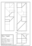
Some years ago, I designed and built a dice tower. I considered releasing proper drawings, but I didn't have a real incentive to do it. Recently, I've been asked if I could draw more readable blueprints than the original paper-and-pen isometric view.

Well, that's done then. The blueprints are now available in PDF under a Creative Commons Attribution-ShareAlike 3.0 Unported License.

Only the core of the tower is drawn there, you need to build a shell around it.

[ Postattu 20. toukokuuta 2010 klo 22.39 | 5 kommenttia | ]

Tiistai, 18. toukokuuta 2010

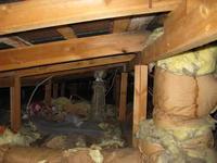
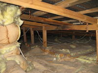
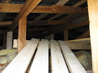
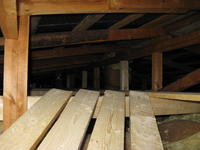
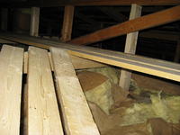
Huoltosilta välikatossa

Kategoriat: [ Askartelu ]

Pekan kanssa rakennettiin eilen huoltosilta välikattoon.

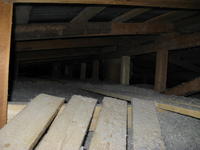
Ennen

Aiemmin siellä näytti tältä.

valikatto_ennen_1

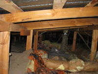
Korkeus on välikaton keskellä 80 cm (kuvassa oikealla puolella). Kuvassa vasemmalla korkeus on noin 60 cm.

valikatto_ennen_2

Oikealla on ilmanvaihtoputki, ja takana näkyy viemärin tuuletusputki.

valikatto_ennen_3

Ilmanvaihtoputken oikea puoli.

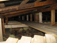
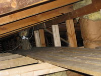
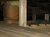
Jälkeen

Ja nyt SE silta.

valikatto_jalkeen_5

Seinässä olevan luukun ja huoltosillan välinen eturamppi on jyrkkä: etäisyys luukusta on alle 70 cm ja silta on 40 cm korkeudella.

valikatto_jalkeen_1 valikatto_jalkeen_7
valikatto_jalkeen_3

Silta itse on 6 m pitkä, jotta se ylettyy viemärin tuuletusputkelle. Ilmanvaihtoputken edessä on pieni tasanne, jotta siihen pääsee käsiksi.

valikatto_jalkeen_2 valikatto_jalkeen_4

Loppujen lopiksi

Päivitetty 18.5.2010

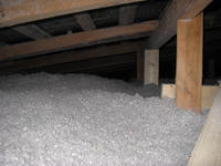
Selluvillaa puhallettiin tänään välikattoon.

valikatto_selluvilla_1 valikatto_selluvilla_2

[ Postattu 18. toukokuuta 2010 klo 19.02 | ei kommenttia | ]

Torstai, 22. huhtikuuta 2010

Antenne TV

Käännös: [ Google ]

Kategoriat: [ Askartelu | TV ]

L'antenne d'intérieur active pour la télé fonctionne relativement bien, sauf quand des conditions indéterminées (en général l'après midi) font que la reception est vraiment mauvaise et que MPlayer plante lors de l'enregistrement. Après avoir lu je sais plus où (probablement dans Make), j'ai étudié la possibilité de construire une meilleure antenne. Je ne suis pas sûr d'y être parvenu, mais celle que j'ai fini par construire fonctionne plutôt bien. En fait le problème principal est que le mur situé entre le salon et la chambre à coucher augmente considérablement le bruit (le rapport signal/bruit donné par la carte DVB est nettement plus bas lorsque l'antenne est dans le salon que dans la chambre à coucher, et le taux d'erreur est plus élevé).

Après une première expérience avec un simple dipôle de 22 cm (prendre un câble d'antenne de 75 ohms, dénuder 11 cm, séparer le blindage de l'âme, torsader le blindage et le replier d'un coté, replier l'âme de l'autre coté pour obtenir un T) où j'ai découvert l'effet du mur, j'ai voulu développer une antenne qui soit adaptée aux fréquences des deux bouquets TNT que je regarde (YLE à 546 MHz et MTV3/Nelonen à 786 MHz).

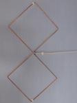
biquad_300_reflector

Les deux fréquences étant éloignées l'une de l'autre, ce n'est pas une tâche facile. J'ai fini par obtenir un résultat théorique plutôt bon avec une biquad munie d'un réflecteur plan (voir le fichier NEC2).

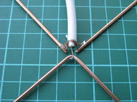
antenne_1 J'ai alors construit la biquad avec une tige d'acier plaquée de cuivre (destinée à la soudure) de 2 mm de diamètre. Le coté d'un petit carré mesure 122 mm.

antenne_2

Je l'ai soudée à 10 m de câble d'antenne 75 ohms. Je comptais mettre l'antenne derrière la porte de la chambre où elle aurait été invisible, mais la réception était bien meilleure à coté de la fenêtre. J'ai donc dû rajouter une rallonge de 3 m.

antenne_3

Je me suis rendu compte qu'installer l'antenne dans la chambre à coucher avec son réflecteur situé 10 cm en arrière n'allait pas être facile (comprendre : ça va dépasser du mur et ça va être très moche). Mais les performances pratiques de cette antenne sans son reflecteur sont semble-t-il suffisamment bonnes (on n'est pas très loin de l'émetteur) : le taux d'erreur a été divisé par 16, et j'espère que ça évitera à la réception de devenir tellement mauvaise que MPlayer plante.

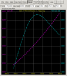
biquad_300

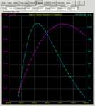
Les performances théoriques (meilleur gain net dans la partie haute de la bande de fréquences que dans la partie basse) contredisent les valeur (qui valent ce qu'elles valent) renvoyées par la carte DVB (taux d'erreur plus faible dans la partie basse de la bande). Je suppose qu'il existe une source de bruit externe plus forte dans la partie haute que dans la partie basse qui explique cette différence.

[ Postattu 22. huhtikuuta 2010 klo 13.27 | ei kommenttia | ]

Tiistai, 24. marraskuuta 2009

Détecteur IR

Käännös: [ Google ]

Kategoriat: [ Askartelu/Arduino ]

Le détecteur IR (QRB1134) ne fonctionne pas très bien pour détecter le déplacement de l'aiguille du compteur d'eau. Le fait qu'il y ait une couche de verre et que le compteur soit sous eau ne doit probablement pas faire partie des paramètres normaux de fonctionnement…

J'ai suivi le schéma à superdroidrobots.com pour le branchement, en ajoutant une LED rouge entre la résistance de 10 kΩ et le collecteur du phototransistor. L'Arduino n'a servi que comme source de tension stabilisée.

L'émetteur IR a une tension de polarisation de 1,7 V et supporte jusqu'à 40 mA, il nécessite donc une résistance de 83 Ω. Avec 110 Ω, on obtient 30 mA. J'ai utilisé deux résistances de 220 Ω en parallèle lors du deuxième test.

Il faudrait essayer en utilisant une entrée analogique de l'Arduino et observer les variations de tension au bornes du capteur pour voir si on arrive à détecter le passage de l'aiguille.

[ Postattu 24. marraskuuta 2009 klo 21.43 | ei kommenttia | ]

Maanantai, 28. syyskuuta 2009

Compteur d'eau

Käännös: [ Google ]

Kategoriat: [ Askartelu/Arduino ]

J'ai enfin essayé de détecter le passage de l'aiguille des décilitres du compteur d'eau en utilisant l'oscilloscope, mais sans succès. Je suppose que le verre diffuse trop les infrarouges, et que l'aiguille est trop petite pour être détectée. Le capteur voit facilement un trait de marqueur noir de 5 mm sur du papier blanc, et dans certaines conditions, un trait de 1,5 mm, mais est incapable de percevoir un trait de 0,5 mm.

compteur_d_eau_1

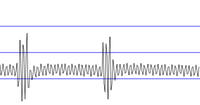
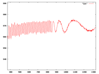
Ce que j'ai réussi à détecter en revanche, c'est la rotation d'une sorte d'hélice à 6 pales qui tourne lorsque de l'eau passe à travers le compteur. J'obtiens un signal oscillant entre 960 et 972 (sur l'échelle de 0 à 1024 de l'ADC de l'Arduino), mais il faudrait mesurer la fréquence pour connaître la vitesse de rotation de l'hélice, et ensuite trouver la relation entre la vitesse de rotation et le débit d'eau.

AJOUT: l'hélice semble faire 6 tours par litre d'eau.

compteur_d_eau_2

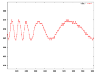
Il y a a priori suffisamment de points pour trouver la fréquence même si le débit d'eau augmente.

AJOUT: la fréquence d'échantillonage maximale par défaut est 9600 Hz (trouvé ). Le compteur ayant un débit maximum de 2500 L/h, ça fait 25 mouvement de pale (1/6 è de tour) par seconde. Si on compte 10 échantillons par mouvement de pale, il faut échantilloner à 250 Hz, ce qui est largement faisable. En pratique, je suppose qu'une fréquence plus faible devrait suffire aussi.

[ Postattu 28. syyskuuta 2009 klo 19.07 | 1 kommentti | ]

Maanantai, 16. maaliskuuta 2009

Bugs!

Käännös: [ Google ]

Kategoriat: [ Askartelu ]

Yesterday late evening I went to the kitchen, switched the light on and… nothing, except a slight buzzing from the switch. I ran to the fuse board and removed a couple of unlabeled fuses (until I found the one for the kitchen, which bore a label). Of course, the fridge is on the same circuit as the light, so I had to pull it out of its corner to grab its power cord, and connect it to one of the sockets in the kitchen (which are on a grounded circuit).

After that, I removed the cover, I took a look at the inside of the swith. It was full of cooked ants… We've been having ants in the kitchen (they came with the house, they visit us at the end of the winter, and should leave when the weather is warmer outside), but I never expects the buggers to walk into the electric switch. Damn stupid animals (which they are, of course, taken individually). So I vacuum-cleaned the switch, then used canned air to spray the last pieces of ant out. But the switch was still not conducting electricity.

The problem was that cooked ants don't conduct electricity very well (I measured about 60 Ω through the switch) and the switch was still buzzing. After a bit of thinking and scratching the contacts with a flat screwdriver (too big for the job), I thought of using a piece of sandpaper, stick it between the contacts, close the switch, and pull. After a couple of times, the switch was better than new (with a resistance of under an Ohm).

Lights are working fine now. But why does this always happen at night, when you have to work with a flashlight in your mouth?

[ Postattu 16. maaliskuuta 2009 klo 21.33 | 5 kommenttia | ]

Torstai, 26. helmikuuta 2009

En Garde

Käännös: [ Google ]

Kategoriat: [ Askartelu | Pelit ]

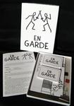
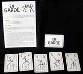
En_Garde-contenu

Knizia a publié en 1993 En Garde, un jeu de cartes qui simule un duel d'escrime. Il a été réimplémenté en 2004 sous le nom de Duell avec quelques cartes supplémentaires, puis réédité en 2008, mais payer 30 EUR (ou 20 pour l'édition de voyage) pour 25 cartes numérotées de 1 à 5, un plateau de 23 cases et 2 pions, ça me paraît de l'abus. Je ne suis pas un artiste, mais pour essayer si le jeu est bien je me suis dit que je pourrais bien fabriquer les composants moi-même.

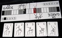
En_Garde-plateau_cartes_pions

Les dessins sur les cartes viennent des cartes de l'édition 2008, d'où j'ai simplement relevé la position des deux bretteurs sous forme de bonshommes « bâtons ». Les cartes ont été imprimées à grand'peine sur des feuilles microperforées.

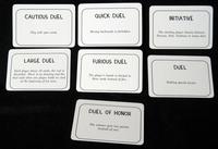
En_Garde-cartes_speciales

Le texte des cartes spéciales est une traduction de l'espagnol vers l'anglais à partir de d'une autre version faite maison.

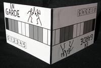
En_Garde-plateau_plie

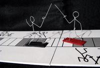
Le plateau est collé à la colle en aérosol sur du carton gris de 2 mm. Les deux moitiés sont assemblées par du gaffer's tape. Il est un peu raté, les deux moitiées ne s'assemblent pas correctement. La prochaine fois, je devrai couper la surface du plateau après collage seulement.

En_Garde-pion

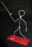
Les pions sont fabriqués à partir de fil de fer zingué de 0,9 mm de diamètre. La tête et les bras sont d'une partie, le tronc une deuxième et les jambes une troisième, et ont été soudées ensemble avec un fer à souder. Le socle est en carton colorié au feutre. J'ai d'abord collé les bonshommes à la cyanoacrylate sur le carton, mais ils n'ont pas tenu, je les ai recollés à la colle universelle transparente (sans eau).

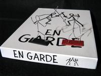
En_Garde-pions_sur_boite En_Garde-pions_sur_plateau

En_Garde-boite

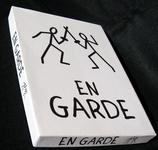
La boite est en carton gris d'1,5 mm. Les coins sont assemblés avec de la bande adhésive transparente de base (qui ne tient pas bien), et la couverture est collée encore une fois à la colle en aérosol.

En_Garde-regles_cartes

Les règles sont copiées de la version de Chris Lawson publiée sur le web.

[ Postattu 26. helmikuuta 2009 klo 10.22 | ei kommenttia | ]

Sunnuntai, 21. syyskuuta 2008

Recumbent Trike

Käännös: [ Google ]

Kategoriat: [ Askartelu ]

Gasoline is expensive, at a current price of about 1.50 EUR/L it costs me currently 950 EUR/year. Especially now that I live closer to work, the consumption is higher because the trip is so short.

The previous plan was to get an electric car, but it would cost a lot and need to keep the old car for longer trips (for example I wouldn't trust the e-car to take us to Tampere, wait 4 weeks on the airport's long-term parking lot and drive us back home). That means more insurance costs, parking space worries and so on.

The current plan is to build a recumbent trike based on one (or two?) old (or new) bycicles. Ready-made devices cost about 2,500 EUR (with one exception at 900 EUR, that's suspicious), home-made may take years to build (I have to learn welding first, but Reijo would probably be happy to teach me) but it may cost less than 500 EUR. Such a trike would be perfect for going to work daily, although coming back from work maybe difficult without electrical assistance (the hill back home is definitely steep).

Another requirement would be to have a protection from rain and snow, and ready-made such trikes cost 4500 EUR (5500 EUR with electrical assistance, that's over 5 years of gasoline at current rate). I have no idea how to build a hull for a trike (most people building trikes seem to live in countries where snow and cold is something that happens to other people). Also, it needs to support an extra seat for a child (this one could be mounted over the back wheel, but getting it below the hull will be difficult.

[ Postattu 21. syyskuuta 2008 klo 19.03 | ei kommenttia | ]

Keskiviikko, 27. elokuuta 2008

De l'interopérabilité des ponceuses

Käännös: [ Google ]

Kategoriat: [ Askartelu ]

Thierry Stoehr voit des formats partout, y compris dans les machines à café. Thierry m'a contaminé, j'ai dernièrement vu des formats dans les ponceuses électriques.

Kulmahiomakone

Pour poncer les surfaces de ma tour à dés, j'ai décidé de m'acheter une ponceuse électrique qui devrait en théorie permettre de poncer une grande surface plane d'un coup. Biltema (pas de lien, faut pas déconner, je vais pas leur faire de la pub gratuite) en vend plusieurs modèles à des prix dérisoires (la qualité est probablement dérisoire, et le salaire des ouvriers qui les ont fabriqués aussi). D'abord, j'étais parti sur le modèle ci-contre. Allant au magasin, je découvre qu'il en existe un deuxième modèle, probablement plus adapté à mes besoins, et que j'avais raté en feuilletant le catalogue (pourtant, il était sur la même page que l'autre…). En y regardant de plus près, je me rends compte que dans le premier modèle, les papiers de verre correspondants sont triangulaires et s'attachent à la ponceuse par un genre de scratch. Ils coûtent 3,25 EUR le paquet de 10.

Tasohiomakone

Sur l'autre modèle (à gauche), les papiers de verre sont rectangulaires, et s'attachent par une sorte de pince. Ils coûtent 2,50 EUR les 10. Et comme il ne s'agit finalement que de morceaux de papier de verre classique, je peux très bien en acheter un paquet de 20 feuilles, qui me donneront 60 morceaux, le tout pour 3,50 EUR, au prix d'un peu de découpage.

Quelle est la morale de l'histoire ? Le premier modèle utilise des consommables dans un format exclusif, difficile à fabriquer soi-même (à cause du scratch et un peu de la forme), et qui coûtent 0,33 EUR la plièce. La deuxième utilise un format ouvert, facile à fabriquer soi-même, et qui coûte en fin de compte moins de 0,06 EUR la pièce, soit six fois moins. Je reconnais que les deux ponceuses n'ont pas le même usage (la première sert à poncer dans les coins, la deuxième sur des surfaces planes), mais pour mon usage personnel à moi que j'ai, les formats ouverts l'emportent haut la main. Comme d'habitude.

[ Postattu 27. elokuuta 2008 klo 23.58 | 2 kommenttia | ]

Autopsy of a Blender

Käännös: [ Google ]

Kategoriat: [ Askartelu | Ruoka | Tiede ]

http://www.braun.com/global/products/fooddrink/foodpreparation/handprocessors/mr6000.html

© Braun.com

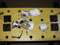
Today, I broke my hand processor (the thing on the left). I was preparing choco noursy v3 and the preparation was too thick. So the motor had difficulties for spinning, and since it could not deliver the energy into movement, it delivererd it as heat. I was aware the the device was heating, because I noticed it earlier, preparing older versions of Choco Noursy. So I was very careful to check that the body of the device was not becoming too hot. I was actually amazed that it didn't heat very much. What I didn't thought about, though, is the speed at which the heat would come out of the device. Now I know: it comes out slowly. Even when the device stopped working, the body was not hot. It became hot a couple of minutes later. But it was already all over (and you could tell simply by the smell of it). Also, there was a noise when you shook it.

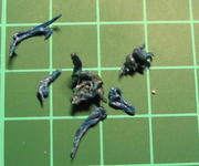
workbench This is when I decided to make an autopsy of the corpse. Since it was all sealed, I had to break it. I finally resorted to saw the body through in order to check where the blue pellets were coming from.

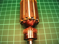
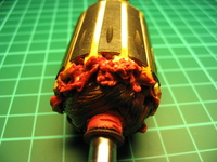
They came from the rotor of the electric motor. Diagnostic: the insulation material melted due to the heat. I'm not sure what it was insulating exactly, probably the different coils of copper wire forming the rotor. The other end of the rotor was also covered with melted red plastic.

So, what have we learned today? If the motor spins much more slowly than maximum speed, it is going to melt soon. Change the gear if possible (yes, I could have done that, the larger bowl of the blender has cogwheels in its hood, and spins more slowly, it is therefore better suited for thick preparations.

blue_pellets rotor-blue rotor-red

[ Postattu 27. elokuuta 2008 klo 23.57 | 1 kommentti | ]

Reliure « dos carré collé » faite-maison

Käännös: [ Google ]

Kategoriat: [ Askartelu | Kirjat ]

Voici comment relier soi-même de manière simple une pile de papiers pour en faire un livre. Typiquement, j'utilise cette méthode pour relier des livres que j'imprime moi-même, comme par exemple ceux que Roland C. Wagner a mis en téléchargement libre. C'est tellement plus confortable que de lire sur un écran d'ordinateur !

J'imprime les livres de manière à placer deux pages A5 sur une page A4, en recto verso (donc quatre pages A5 sur une feuille A4), puis je coupe au milieu avec un massicot, en prenant les feuilles par paquets d'une dizaine. Il faut si possible couper le plus au milieu de la page possible, afin que la tranche du livre, une fois toutes les pages rassemblées, soit la plus régulière possible. On peut compenser une irrégularité d'un ou deux millimètres en remplissant avec de la colle, mais si le trou est plus profond, il faudra mettre de nombreuses couches de colle, ou utiliser une colle de type polyuréthane (PU) qui gonfle en séchant (je n'ai jamais essayé).

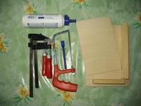
Matériel

Reliure
materiel_reliure
  • colle blanche (à papier ou à bois, de type PVA)
  • spatule à colle
  • ficelle
  • petite scie à dents fines (à métaux)
  • deux lattes de bois ou une presse faite maison
  • deux serre-joints
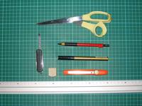
Couverture
materiel_couverture
  • carton de couleur (260 g/m² par exemple)
  • feutre (par exemple doré)
  • règle métallique
  • cutter
  • crayon à papier
  • plastique transparent autocollant

Ma presse

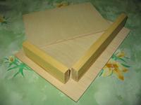
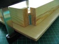
presse Elle se compose d'un morceau de contreplaqué (250 × 180 × 6,5 mm) un peu plus grand qu'une page A5 et de deux tasseaux (14 × 55 mm, 218 mm et 116 mm de long) collés sur la plache de manière à former un angle droit. Un deuxième morceau de contreplaqué (220 × 145 × 6.5 mm) vient recouvrir exactement l'emplacement entre les deux tasseaux.

On peut se passer de la presse et utiliser à la place deux lattes de bois pour serrer la pile de papier (voir les photos). L'intérêt de la presse est de pouvoir « taquer » le papier contre les tasseaux et avoir des pages les mieux alignées possibles. Sans la presse, il faut être à deux pour taquer les pages, placer les lattes puis les serre-joints.

Collage des page

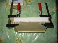
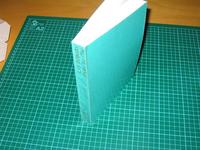
tranche_collee Rassembler les pages (dans le bon ordre !) de manière à ce que les trois bords extérieurs des pages soient bien alignés. Ceci permet d'éviter de devoir couper les bords une fois la reliure achevée, chose impossible sans un massicot capable de couper droit une épaisseur importante (hors de prix pour un particulier). Serrer les pages ensemble soit en plaçant les deux lattes de part et d'autre de la pile de feuilles à 5mm du quatrième bord, soit en plaçant les feuilles dans une presse comme celle que j'ai fabriquée. Serrer avec les serre-joints.

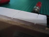
encoches Couper des encoches dans la tranche du livre à l'aide de la scie, sur une profondeur de 1 à 2 mm.

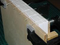
ficelles Enduire la tranche de colle blanche et placer un morceau de ficelle dans chaque encoche. Les morceaux de ficelle doivent dépasser d'un centimètre environ de chaque coté.

Laisser sécher la colle pendant 15 minutes environ, puis repasser une couche de colle. Laisser sécher 12 heures au moins.

Couverture

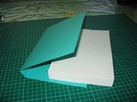
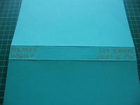
couverture Découper un morceau de carton suffisamment grand pour couvrir le livre, puis le plier de sorte qu'il s'emboite sur le livre.

texte Écrire le texte adéquat sur la tranche (si on utilise un feutre doré à base de peinture, il faut laisser sécher le texte plusieurs minutes).

lignes Tracer deux lignes à l'aide d'un objet fin et non tranchant de part et d'autre de la tranche sur l'extérieur de la couverture. Ceci permet à la couverture de s'ouvrir sans exercer de contrainte sur le collage près de la tranche. Ces lignes ont un nom technique, mais je ne m'en souviens plus.

presse_couverture Enduire l'intérieur de la couverture de colle, entre les deux lignes précédemment tracées et emboiter rapidement le livre dans la couverture. Cette étape est délicate, car si on met trop de colle, le carton gondole, et si on met trop peu, elle sèche trop vite. Placer le livre dans la presse afin de maintenir les parties collées sous pression.

Laisser sécher pendant plusieurs heures.

plastique_decoupe Découper un morceau de plastique transparent autocollant suffisamment grand pour couvrir la couverture et se rabattre sur l'intérieur de la couverture. Coller le plastique sur le livre.

Et voilà ! Le livre est suffisamment solide pour être lu plusieurs fois sans que les pages ne tombent.

livre_termine livre_interieur

Modifié le 10/12/2007: Un lien vers un autre tutoriel sur la reliure maison par Andrew Seltz. Il suggère en particulier de poncer la tranche du livre avant de l'encoler (avec un papier de verre à grain 200 ou 300).

[ Postattu 27. elokuuta 2008 klo 23.57 | 64 kommenttia | ]

Ironing Card Sleeves

Käännös: [ Google ]

Kategoriat: [ Askartelu ]

After successfully resizing a card sleeve, I wanted to try something else: card lamination using a card sleeve and an iron (the one you use to get the creases off your clothes). I put a card in a sleeve, put it between two layers of baking paper, set the iron to the “cotton” and ironed it on both sides, on top of a piece of mirror (because it's flat and hard).

Well, it doesn't work. What you get is a card sleeve that has lost its shine and its transparency in some areas and doesn't adhere to the card (actually, it does adhere in some places, but on most of the surface it doesn't, especially on the laser-printed parts).

[ Postattu 27. elokuuta 2008 klo 23.56 | ei kommenttia | ]